

1. Define cooling as a sold-capacity constraint
A data centre sells a service that depends on continuous removal of heat. The commercial product can be a powered shell, colocation cabinet, dedicated hall, AI cluster or managed compute service. Each product carries a power density, inlet condition, availability, ramp, maintenance and acceptance obligation. Cooling capex should therefore begin with the product schedule rather than a preferred mechanical system.
The critical quantity is usable IT capacity under the facility's actual operating envelope. A hall rated at 20 MW on an electrical schedule may support less sellable capacity when rack density, ambient heat, water constraints or cooling redundancy become binding. The board should distinguish connected power, installed cooling, commissioned cooling, customer-accepted cooling and available IT service.
Cooling also sets the pace of customer conversion. A customer may require defined facility-water temperature, pressure, chemistry, redundancy, leak detection and maintenance procedures before accepting a liquid-cooled deployment. Air-cooled customers can require different containment, humidity and particulate controls. The facility needs a product catalogue that states what can be delivered today and what requires conversion capex.
The decision objective is durable capacity. The selected architecture should serve an evidenced opening load, preserve a practical route to higher density, remain operable during design heat, control water and energy exposure, and support the customer and financing contracts. A narrow first-cost comparison misses these obligations.
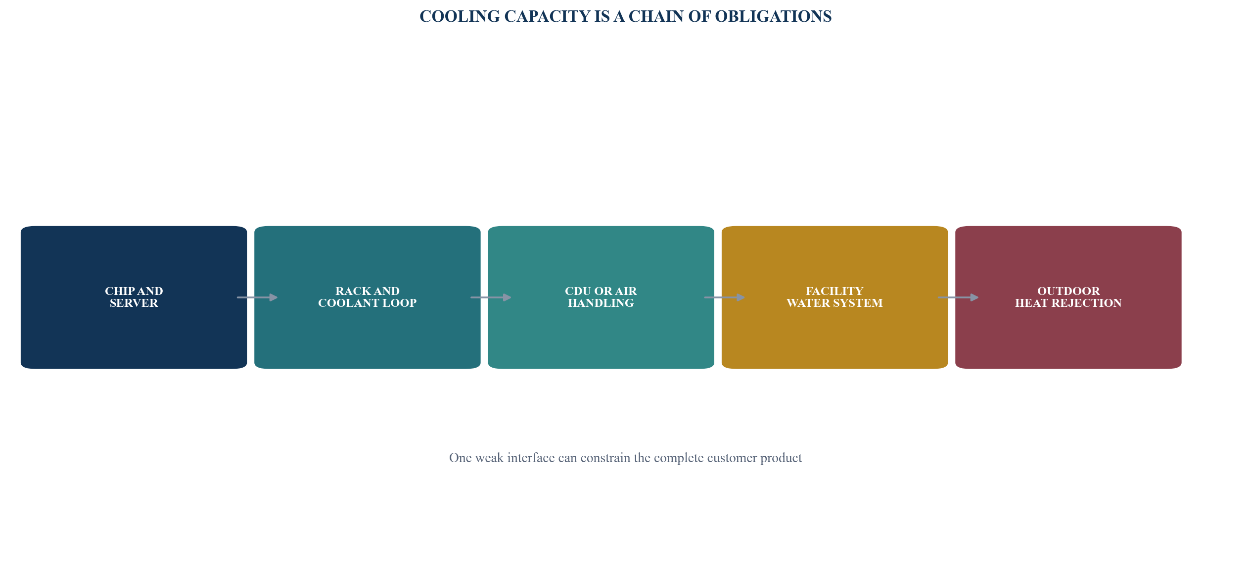
Sellable capacity depends on every thermal interface from silicon to the external heat sink.
2. Establish the evidence boundary before selecting equipment
Published standards and disclosed deployments provide reference points. They do not replace a project-specific design. ASHRAE's Thermal Guidelines for Data Processing Environments provides common environmental guidance for equipment and facilities, including air- and liquid-cooled environments. The United States Department of Energy's 2024 guide covers IT systems, environmental conditions, air management, cooling systems and heat recovery. These materials support disciplined design questions while equipment warranties and project engineering remain controlling.
Singapore's SS 697:2023 tropical data-centre standard provides a methodology for gradually raising operating temperatures in a tropical climate. IMDA states that the standard supports operation at 26 degrees Celsius and above and cites potential cooling-energy savings of 2 to 5 per cent for each 1 degree Celsius increase. IMDA also reports a Digital Realty trial in two 4.5 MW halls where a 2 degree increase corresponded to an approximate 2 to 3 per cent reduction in total energy use during the trial. These are disclosed examples, not project forecasts.
The European Union's 2024/1364 delegated regulation creates a common reporting framework for qualifying data centres. It includes power usage effectiveness, water usage effectiveness, energy reuse factor and renewable energy factor, and requires temperature-set-point and water data. The regulation therefore illustrates how cooling decisions can become reporting and stakeholder evidence. It applies within its legal scope and does not establish a Gulf reporting obligation.
Abu Dhabi's Department of Energy has published policy supporting efficient water use, water reuse and cooling-system efficiency. Its district-cooling water policy considers recycled, desalinated and sea water subject to feasibility, quality, discharge and environmental requirements. A data-centre project should confirm whether any policy, water source or district-cooling route applies to its own activity and location.
Table 1. Published evidence and project confirmation boundary
| Source | Evidence supported | Decision use | Project confirmation required |
|---|---|---|---|
| ASHRAE thermal guidance | common environmental and liquid-cooling concepts | define equipment and facility questions | supported classes, warranties, site limits and operating procedures |
| U.S. DOE 2024 design guide | energy-efficient design practices and liquid-cooling pathways | compare system architecture and metrics | engineer's design, climate model and priced equipment |
| Singapore SS 697:2023 | tropical higher-temperature methodology | operating-envelope and test planning | equipment support, customer acceptance and local climate study |
| EU 2024/1364 | PUE, WUE, ERF, REF and reporting boundaries | measurement and disclosure design | legal scope, meter plan and reporting responsibility |
| Abu Dhabi DoE policies | energy and water efficiency direction and water-source considerations | water-route and stakeholder diligence | project applicability, source, quality, capacity and approvals |
| OCP specifications | vendor-neutral interface work for liquid-cooling components | interoperability and procurement questions | final component qualification and system integration |
A reference point supports diligence; it does not determine the live design.
3. Translate the customer roadmap into thermal duty
The cooling design should begin with an IT deployment schedule by customer, hall, rack type and date. Each entry should state electrical input, expected heat captured by liquid, residual heat to air, coolant conditions, redundancy, diversity and acceptance criteria. A single average watts-per-rack assumption can conceal material differences within one facility.
AI infrastructure illustrates the change. NVIDIA's published DGX GB200 user guide describes an NVL72 rack with approximately 120 kW of power consumption, liquid-cooled compute and switch trays, manifolds, cold plates and leak detection. The public design shows why rack-scale equipment, facility liquid loops and operating controls need coordinated readiness. The specification of one platform does not determine the future mix of a data centre.
The roadmap should include a distribution rather than one peak. Low-density storage, network and conventional compute can remain air cooled. Accelerated compute can use direct-to-chip liquid cooling with residual air cooling. Other workloads can require rear-door heat exchangers or immersion. Shared infrastructure must manage the simultaneous mix.
The sponsor should classify certainty. Signed customer orders have a different weight from pipeline conversations, vendor roadmaps and speculative future density. Base capex should serve the contracted or strongly evidenced load. Enabling works can preserve conversion rights for plausible growth. Capacity that depends on uncontracted equipment can sit behind a separate release gate.
4. Compare technologies as complete systems
Air cooling transfers heat from the equipment to room air and then to coils or refrigerant systems. Its supply chain and operating practices are mature. Fan energy, airflow paths and practical rack density can become constraints. Containment and temperature discipline materially affect performance.
Evaporative systems can reduce compressor energy by using water evaporation to reject heat. Their energy advantage should be weighed against water source, quality, treatment, blowdown, drift, hygiene, plume, discharge and drought conditions. Hot dry conditions differ from hot humid conditions. Hour-by-hour wet-bulb data matters.
Chilled-water systems can serve air handlers, rear-door units and cooling distribution units. Chiller efficiency changes with ambient conditions and water temperatures. Plant modularity, minimum load, part-load performance, pumping, redundancy and maintenance influence lifecycle economics.
Direct-to-chip cooling moves heat through cold plates and a liquid loop to a CDU and facility system. It can support high-density racks and warmer water. It also creates new interfaces around coolant chemistry, pressure, connectors, leak detection, controls, residual air load and maintenance. Open Compute Project work on cold plates and quick disconnects is relevant to interoperability diligence.
Immersion cooling places equipment in dielectric fluid. It can remove high heat loads and reduce reliance on server fans. Hardware compatibility, fluid management, servicing, fire strategy, material compatibility, warranty, customer acceptance and residual value require specific diligence. A technology should not be selected solely from its theoretical heat-transfer capability.
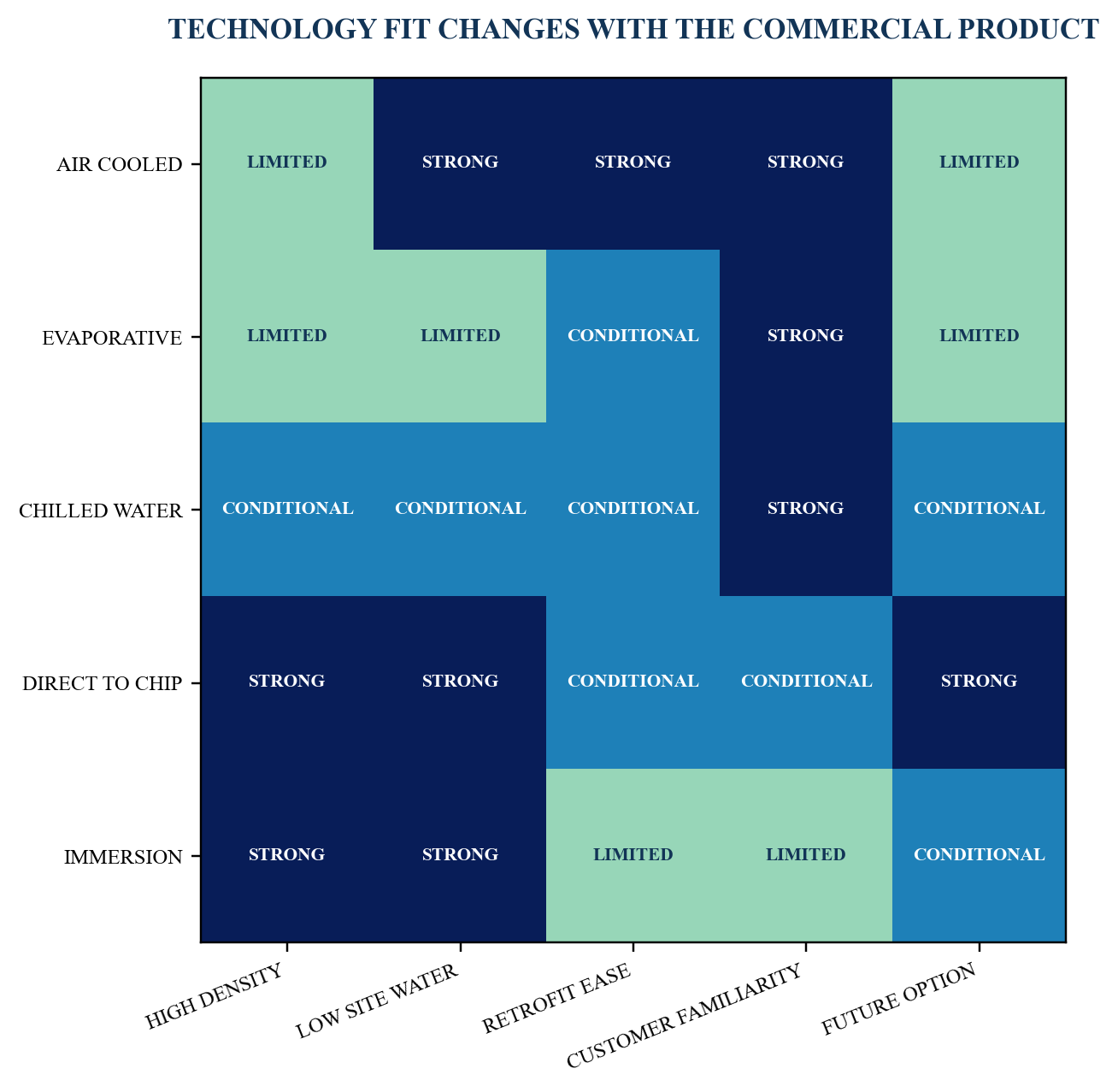
Ratings are illustrative; live workload, climate, engineering and customer requirements govern.
Table 2. Cooling pathway and principal diligence questions
| Pathway | Primary strength | Binding diligence | Conversion issue |
|---|---|---|---|
| contained air | mature operations and broad equipment support | rack density, fan energy, airflow and peak ambient | space, duct, coil and fan capacity |
| evaporative | lower compressor duty in suitable weather | water source, quality, wet bulb, treatment and discharge | water infrastructure and community acceptance |
| chilled water | flexible central plant and multiple terminal types | chiller curve, pumping, redundancy and part load | pipe capacity and supply temperature |
| direct to chip | high heat capture near silicon | CDU, chemistry, pressure, connectors and residual air | rack manifolds, facility loop and commissioning |
| immersion | high heat removal and reduced server fans | hardware, fluid, service model, fire and warranty | customer acceptance and equipment portability |
Every pathway should be assessed at the chip, rack, room, plant and heat-rejection boundaries.
5. Design to an hourly climate file
Heat stress is an operating distribution. A design dry-bulb point, coincident wet bulb, solar load, humidity, dust event, wind condition and future climate allowance can produce different constraints. Monthly averages do not establish peak capacity or annual energy.
The mechanical model should calculate plant duty for every hour under the expected IT ramp. It should identify compressor hours, economiser hours, cooling-tower approach, dry-cooler capacity, pump and fan power, water consumption, redundancy availability and any capacity derating. The result should be reconciled to equipment performance data at the relevant temperatures.
Future climate should be a scenario. The board can test higher dry bulb, higher coincident wet bulb, more extreme hours, dust-related fouling and reduced water availability. These are project assumptions until supported by an approved climate basis. The model should show which components bind and how much sellable capacity remains.
Heat waves also affect the surrounding system. Grid peaks, water demand, maintenance access and equipment lead times can become more difficult simultaneously. The operating plan should identify seasonal spares, chemical inventory, cleaning, staffing and customer communication before the high-risk period.
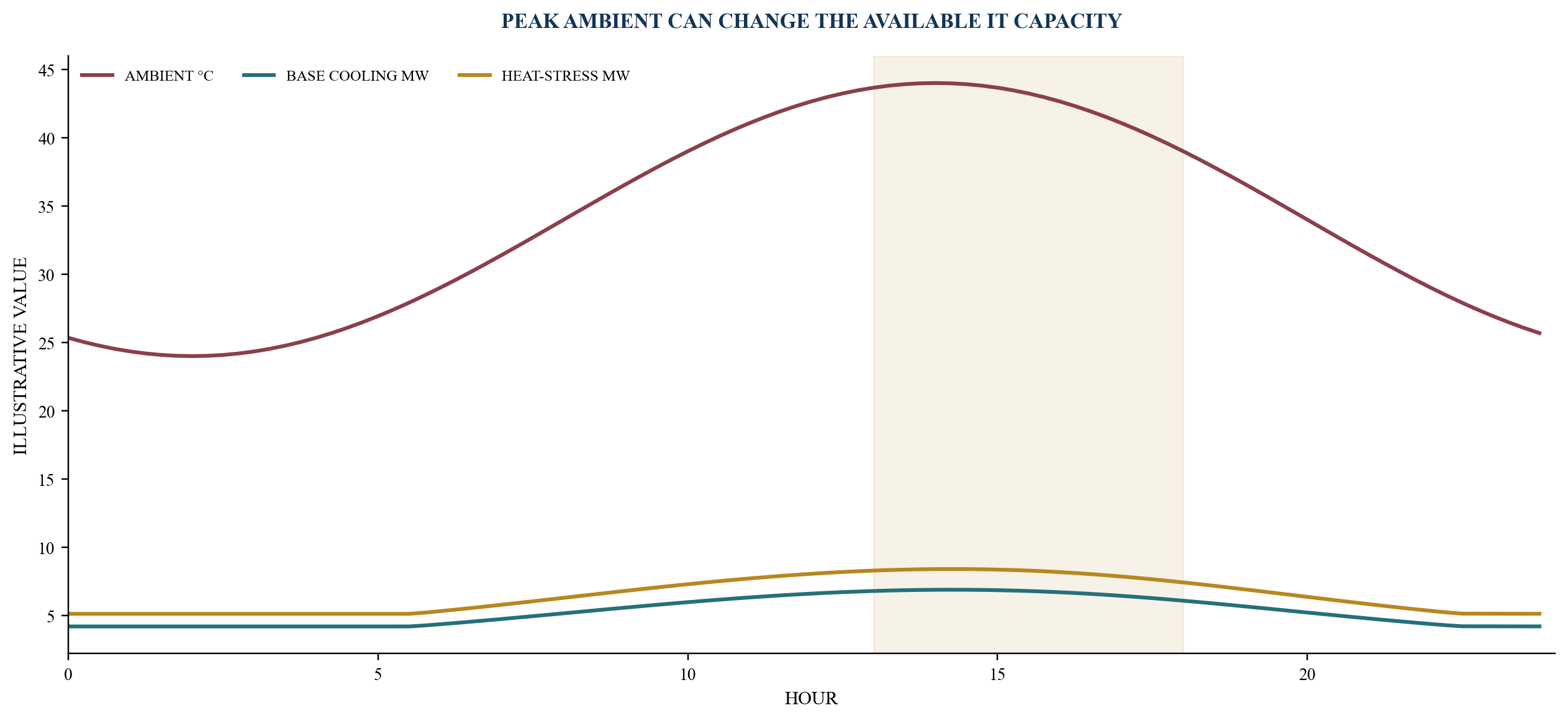
Values are management assumptions for method demonstration and do not represent a project climate file.
6. Treat water as a contracted input and social constraint
Water use should be measured at a defined boundary. The EU reporting methodology expresses WUE as total water input divided by IT energy. The metric can support comparison when boundaries and categories are consistent. It does not capture every upstream water effect, local scarcity or water-quality burden.
An evaporative design requires source capacity, pressure, quality, treatment, storage, discharge and contingency. Potable, desalinated, recycled and sea-water pathways can carry different capital, energy, chemical, corrosion and environmental consequences. Abu Dhabi's published district-cooling policy shows why source feasibility, quality and discharge should be assessed together.
The United States DOE identifies operational measures such as temperature and humidity control, cycles of concentration, treatment and direct liquid cooling. It states that moving from three to six cycles of concentration can reduce cooling-tower makeup requirements by 20 per cent and blowdown by 50 per cent under the cited best-practice example. A live facility needs water-chemistry analysis and operating approval before adopting a target.
Closed-loop liquid cooling at the rack does not automatically mean zero site water. The facility can still reject heat through a cooling tower. Conversely, an air-cooled heat-rejection system can reduce operational water and use more electricity during hot hours. The investment committee should review water and energy together.
7. Underwrite PUE and WUE as curves
PUE divides total facility energy by IT energy. WUE divides site water use by IT energy under the chosen boundary. Both metrics change with utilisation, weather, plant staging, IT mix and maintenance. A single annual target can conceal critical hourly and seasonal behaviour.
The financial model should calculate PUE and WUE across load steps and climate bins. A plant designed for a future 40 MW load can operate inefficiently at 8 MW if modules, pumps and controls cannot stage well. A low PUE in mild weather can coexist with material capacity derating during extreme heat.
The customer tariff should state whether auxiliary cooling energy is included in capacity or consumption charges. It should also identify any water pass-through, change mechanism and measurement boundary. A sponsor can otherwise absorb cost that rises with ambient conditions or customer density.
European reporting rules provide a useful measurement framework through PUE, WUE, energy reuse and renewable energy indicators. A Gulf project can adopt comparable discipline voluntarily while confirming its actual regulatory and customer obligations.
Table 3. Metric tree for cooling investment decisions
| Metric | Calculation or evidence | Commercial use | Principal limitation |
|---|---|---|---|
| PUE | total facility energy divided by IT energy | tariff, efficiency and capacity planning | sensitive to load, weather and boundary |
| WUE | site water input divided by IT energy | water planning and disclosure | does not express local scarcity by itself |
| cooling capacity | commissioned duty at design condition | sellable IT capacity | depends on redundancy and ambient condition |
| heat capture ratio | heat removed by liquid relative to IT heat | residual-air and CDU design | equipment-specific and operating-dependent |
| supply temperature | delivered coolant or air condition | equipment acceptance and plant efficiency | must follow equipment and customer limits |
| availability | time cooling product remains within specification | service level and financing | measurement and exclusions can differ |
Metric definitions and boundaries should be fixed before bids and customer commitments.
8. Separate chip, technology and facility loops
Direct liquid cooling creates at least three control domains: the technology cooling system at the server, the facility coolant distribution system and the external heat-rejection system. A heat exchanger or CDU can separate fluids, pressure and chemistry. The interface schedule should state ownership, operating limits and responsibility at each boundary.
The technology loop can carry treated water, glycol mixture or another approved fluid. Materials, corrosion, biological control, filtration and conductivity should be matched to equipment requirements. The facility loop has its own water quality, pumping, expansion, make-up and maintenance obligations.
Pressure, temperature and flow should be measured at the rack or CDU boundary. Differential pressure can affect distribution across many racks. A high-density cluster can require dynamic flow control during compute changes. Controls should coordinate pumps, valves, CDU operation, chillers or dry coolers and alarms.
Residual heat remains important. NVIDIA's published rack guide describes liquid-cooled compute trays while other components use air cooling. The facility should quantify the liquid-captured fraction and size residual air systems for the actual configuration. Removing room air capacity too aggressively can constrain network, storage or auxiliary equipment.
9. Make leak and fluid management financeable
Liquid near high-value computing changes the failure catalogue. The system needs component qualification, pressure testing, flushing, cleanliness control, leak detection, isolation, drainage, spill response and repair procedures. NVIDIA's published guide highlights leak detection as part of system protection. OCP specifications help frame component-level questions without replacing system commissioning.
The contract matrix should allocate responsibility among the server vendor, rack integrator, CDU supplier, mechanical contractor, facility operator and customer. A leak can originate in equipment, a connector, hose, manifold, heat exchanger or facility pipe. Fault location and access need agreed procedures.
Insurance diligence should address physical damage, business interruption, contamination, escape of liquids, equipment replacement and delay. The insurer may require approved components, inspection, maintenance and incident records. Coverage terms and exclusions should be reviewed before the design is frozen.
Operating data should support early warning. Flow imbalance, pressure decay, conductivity, moisture sensors and make-up volume can indicate a developing issue. Alarm thresholds, authority to isolate and customer communication should be tested during commissioning.
10. Preserve modularity and conversion rights
A mixed-load campus can use zones. Conventional halls can retain efficient air cooling. AI-ready zones can receive larger pipe headers, CDU space, structural loading, drainage, controls and external heat-rejection capacity. The sponsor can install some equipment at opening and preserve connection points for later expansion.
Conversion rights should be physical and contractual. A nominal allowance on a drawing has little value when route space, valve locations, floor loading, controls or shutdown windows make installation impractical. The design should show isolation boundaries and a construction sequence that protects operating customers.
Technology neutrality requires interface discipline. Pipe size, temperature class, pressure, chemistry, quick disconnects, telemetry and control protocols should accommodate more than one approved vendor where practical. OCP's vendor-neutral cold-plate and connector work illustrates the value of common interfaces. The final procurement still requires qualified equipment and integrated testing.
The expansion schedule should connect capex to customer evidence. Common headers and plant space may be early enabling works. CDUs, rack manifolds and incremental heat rejection can follow a signed order or binding capacity reservation. This staging protects cash while preserving speed.
Table 4. Conversion-ready design schedule
| Component | Opening provision | Expansion right | Release evidence | Stranding risk |
|---|---|---|---|---|
| pipe corridor | reserved route and structural allowance | install additional supply and return | signed density roadmap | route consumed by other services |
| headers | sized or valved connection points | add modular loop capacity | customer reservation and hydraulic model | oversize impairs part-load operation |
| CDU area | power, drainage, access and controls | install vendor-qualified modules | equipment selection and acceptance plan | vendor footprint or interface changes |
| heat rejection | modular bays and connection stubs | add dry coolers, towers or chillers | climate and load model | land or acoustic limits bind |
| residual air | contained base system | add terminal units or fan capacity | measured liquid heat capture | liquid ratio lower than assumed |
| controls | extensible points and protocols | integrate new devices and alarms | approved sequence and cyber review | proprietary lock-in |
Enabling works should have an evidenced future use and a clear release gate.
11. Gate capex through design maturity
Cooling capex should move through defined evidence gates. Concept selection establishes the workload, climate basis, water pathways, candidate architectures and site constraints. Basis of design fixes the thermal duties, redundancy, temperatures, fluid boundaries, metering and control principles.
Detailed design should close hydraulic calculations, equipment schedules, structural loads, electrical demand, acoustic impact, drainage, treatment and commissioning. Procurement follows qualified bids, interface review, lead-time confirmation, warranty terms and lifecycle support.
Factory and site tests should be linked to payment. Witnessed performance at relevant load and temperature, pressure tests, controls, failover and water-quality records provide stronger evidence than equipment delivery. Customer acceptance can require a separate integrated systems test.
Contingency should follow unresolved risk. Early estimates carry design, quantity, interface, escalation and programme uncertainty. The contingency can reduce as evidence closes. Releasing the entire equipment package before customer, water and interface requirements are fixed creates avoidable change exposure.
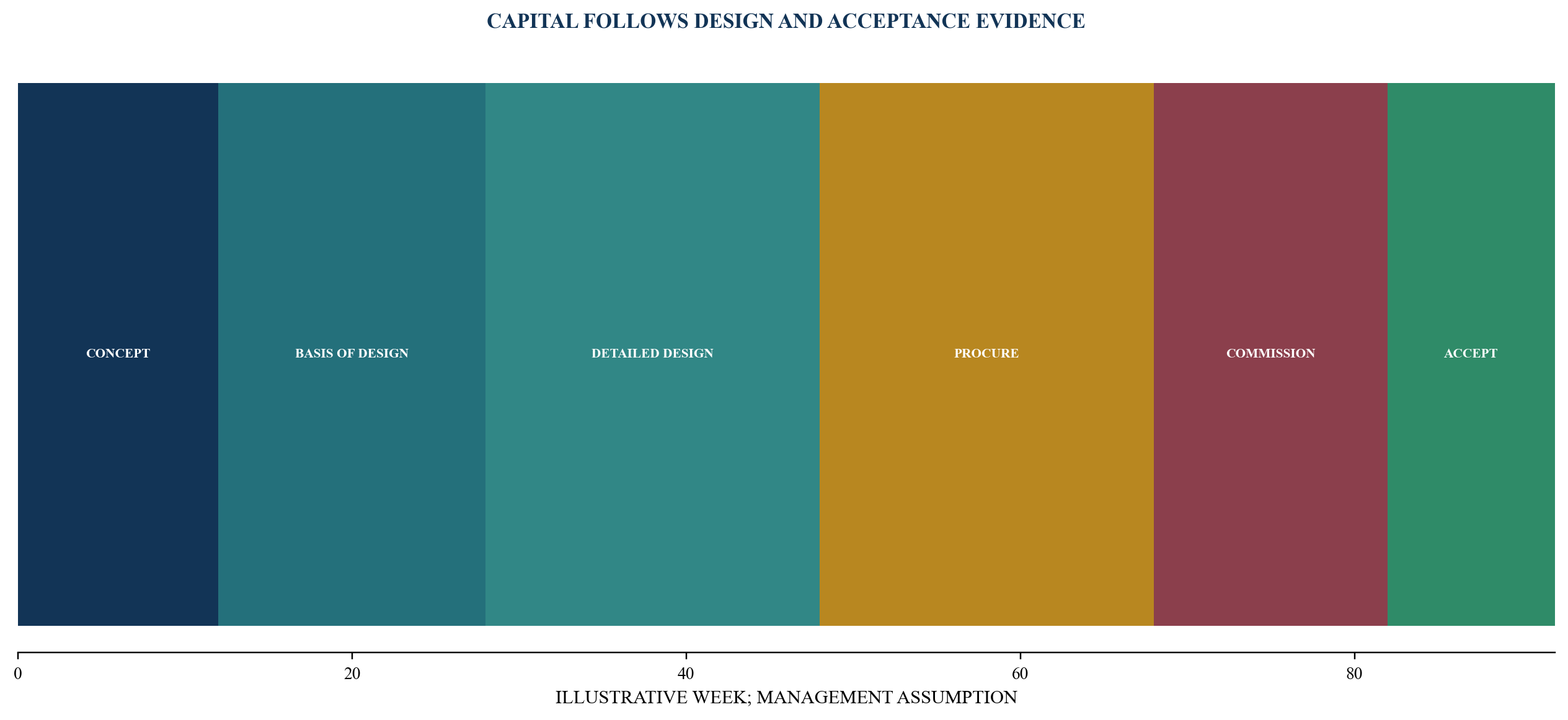
Capital release follows evidence from product definition through customer acceptance.
12. Procure performance at the project boundary
An equipment schedule should state rating conditions, not only nameplate capacity. Chillers, dry coolers, cooling towers, pumps, CDUs and air handlers need performance at the project's temperature, humidity, altitude, fouling and fluid conditions. The sponsor should request complete curves and part-load data.
The procurement package should separate supply, installation, controls, commissioning, spares and lifecycle service. Interface responsibility should be explicit. A chiller supplier can meet its unit performance while the plant misses system efficiency because of pumps, towers, controls or water conditions.
Lead times and substitution rights need governance. A proposed substitute should pass thermal, hydraulic, electrical, space, acoustic, control, maintenance and warranty checks. A faster component can create downstream redesign or a proprietary dependency.
Performance damages and remedies should follow measurable failure. Capacity, efficiency, water use, noise, availability and completion can each have different tests and consequences. Legal and engineering advisers should align the specification, test method, exclusions and remedy.
13. Commission the complete thermal chain
Commissioning should begin with design review and continue through operation. Factory tests can cover equipment controls and stated performance. Site tests should verify installation, cleanliness, pressure, flow, sensors, communication, alarms, power failure, redundancy and recovery.
Integrated systems testing should follow the customer service. A simulated rack or load bank can exercise heat from the technology boundary through the heat-rejection system. The test should include peak ambient assumptions through an approved method when actual weather is milder.
Failure scenarios should be witnessed. These can include pump, CDU, chiller, cooling tower, dry cooler, power feed, sensor, communication and water-source loss. The system should transfer safely within its operating limits. Test procedures need authority, abort criteria and equipment protection.
The acceptance pack should contain calibrated instruments, raw data, calculations, exception logs, corrective work and retest results. Baseline PUE and WUE measurement should use fixed boundaries. The pack becomes evidence for customers, insurers, lenders and operations.
14. Align customer, operator and supplier contracts
The customer contract should define the cooling product. Relevant terms can include rack density, supply temperature, pressure, fluid, residual air, availability, maintenance, expansion, meter data, water charges, acceptance and change. The customer's equipment warranty and operating procedure should align with the facility design.
The operating contract should allocate routine inspection, chemistry, treatment, filter replacement, leak response, spares, cleaning and seasonal readiness. Responsibility should follow the interface matrix. The operator needs access to supplier data and training.
Supplier warranties can contain fluid, temperature, maintenance and consumable conditions. These obligations should flow into operating procedures and customer rules. A warranty that cannot be preserved under the intended service has limited financing value.
Change control matters because server generations can alter flow, temperature and heat-capture requirements. The contract should require technical review before a customer substitutes equipment or increases density. The provider should retain a route to reprice material capex or utility effects.
15. Finance only commissioned and accepted capacity
Lenders and investors should distinguish enabling works, installed equipment, commissioned duty and customer-accepted service. Cooling capex can support debt when scope, price, delivery, tests, warranties, operating capability and revenue alignment are sufficiently evidenced.
The base case should use sellable capacity at the relevant heat and redundancy condition. It should avoid assuming that all electrical capacity becomes IT revenue. Derating, residual air, maintenance, water restrictions and customer mix can reduce the available product.
Capex facilities can use milestone draws against design completion, equipment delivery, installation, commissioning and acceptance. Retention or reserves can support unresolved performance. Cost-overrun support should reflect the remaining interface and programme risks.
Technology change creates residual-value questions. A proprietary loop, specialised fluid or unsupported connector can narrow the buyer pool. Modular plant, documented interfaces, multi-vendor maintenance and conversion rights can support asset liquidity. Each credit committee applies its own diligence and approval.
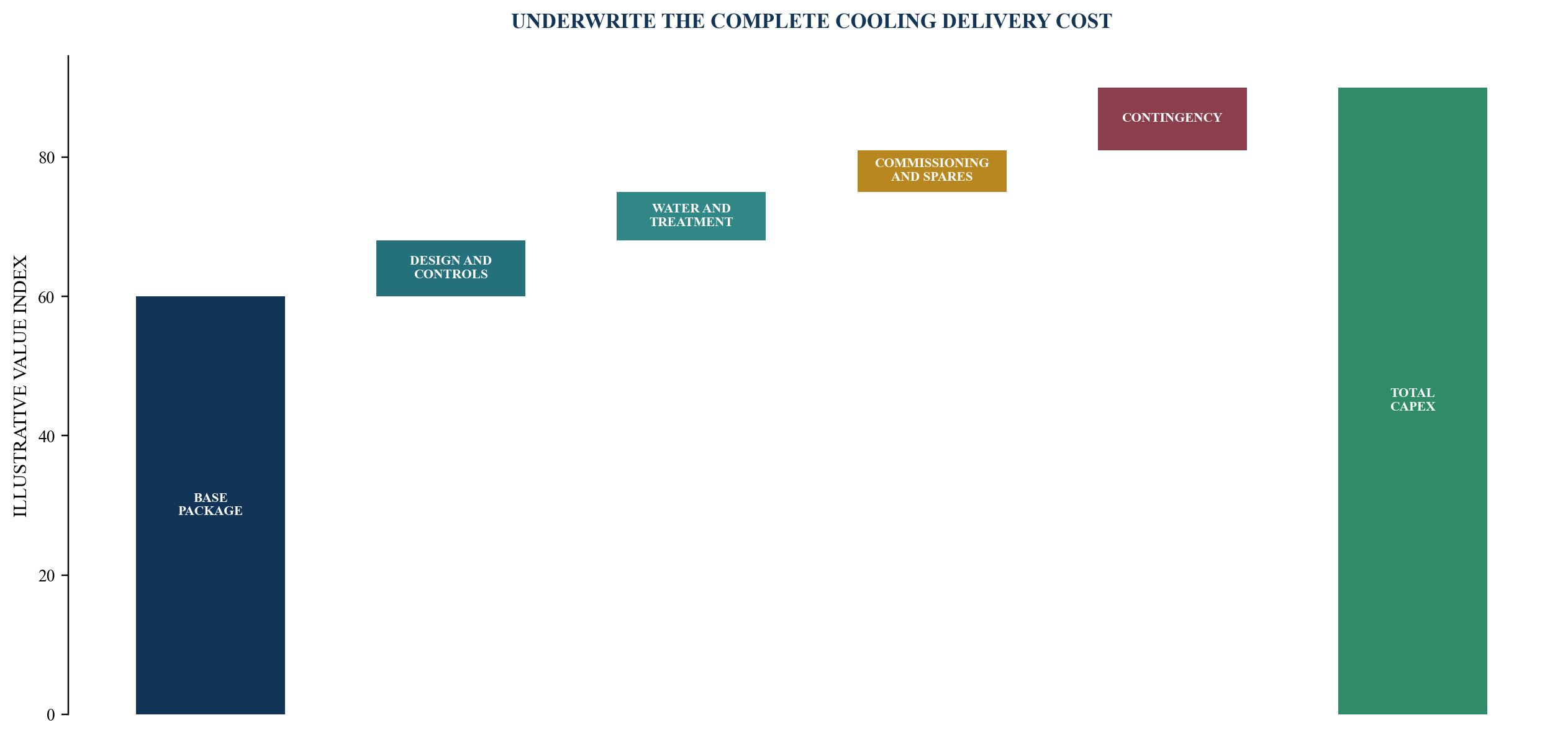
Values are management assumptions and do not represent a project budget or financing offer.
16. Model a complete technology decision
The worked case assumes a 24 MW opening IT load, a 32 MW contracted expansion path and a 40 MW enabled ultimate configuration. It assumes a mixed portfolio that begins with conventional and accelerated compute and increases its liquid-cooled share over time. These values are management assumptions for method demonstration.
The technology model compares a contained-air base, an evaporative-assisted pathway, a modular chilled-water system and a hybrid direct-to-chip design. It calculates equipment, distribution, controls, water, commissioning, spares, maintenance, energy, water and conversion cost. The model applies hourly ambient bins and load steps.
The base decision can select a hybrid architecture: efficient air cooling for conventional loads, conversion-ready liquid infrastructure, modular CDUs and dry or water-assisted heat rejection selected by zone. This is an illustrative result. A live decision depends on customer commitments, climate, water, land, equipment and priced bids.
The model should state physical quantities. It should show rack count, density distribution, liquid heat-capture ratio, facility supply temperature, flow, peak heat rejection, residual-air duty, annual compressor, fan and pump energy, and water use. Financial summaries without these drivers are difficult to audit.
Table 5. Illustrative cooling investment assumptions
| Input | Base assumption | Downside | Live evidence required |
|---|---|---|---|
| opening IT load | 24 MW | 18 MW | executed customer ramp |
| contracted expansion | 32 MW | 24 MW | capacity reservations and acceptance terms |
| enabled ultimate load | 40 MW | 32 MW | master plan and utility capacity |
| liquid-cooled share at opening | 35% | 20% | equipment schedule |
| liquid-cooled share at expansion | 65% | 45% | customer and vendor roadmap |
| total cooling capex | USD 90m | USD 112m | design, bids and contingency |
| annual cooling energy | 42 GWh | 55 GWh | hourly simulation and tariff |
| commissioning period | 14 weeks | 24 weeks | integrated test programme |
All values are management assumptions for method demonstration only.
17. Stress heat, water, customer mix and conversion
The principal downside is a combined scenario. Higher peak ambient can reduce dry-cooler capacity and increase compressor duty. Lower water availability can restrict evaporative operation. A lower liquid-cooled share can leave expensive facility loops underused. A higher share can exceed residual-air, CDU or heat-rejection capacity.
Customer delay affects both utilisation and part-load efficiency. A large plant can carry fixed operating cost before IT revenue ramps. The model should stage modules and test minimum efficient load. It should also carry interest during delay and cash reserves.
Technology substitution can require new manifolds, CDU settings, fluids or controls. The conversion case should include design, shutdown, temporary cooling, customer testing and lost capacity. A simple equipment-cost allowance understates commercial disruption.
Water and electricity prices should move separately. A design that saves water can consume more peak electricity. A design that reduces compressor duty can depend on a water source with treatment and discharge cost. The board should view annual cost, peak system exposure and local resource impact together.
The zero-customer case should value alternative uses. Common plant, routes and modular bays can serve another configuration. Highly specialised equipment can have a narrower resale or redeployment path. Residual value should remain conservative until a market or alternate use is evidenced.
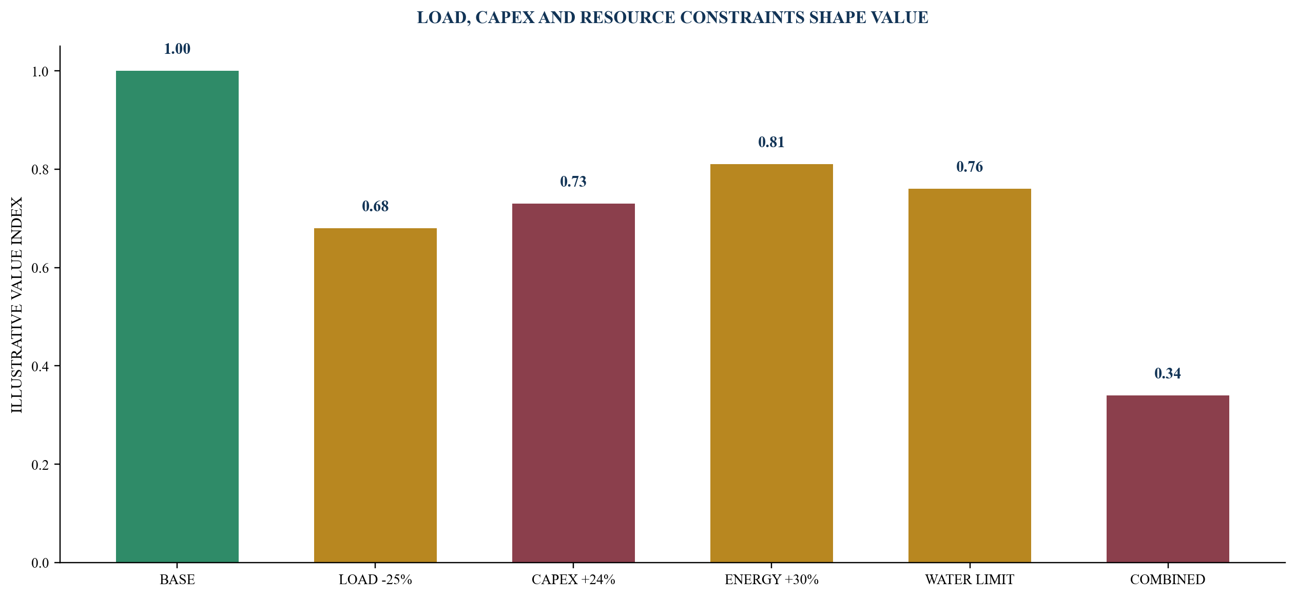
Values are management assumptions and show directional sensitivity rather than a forecast.
18. Build a cooling investment data room
The commercial folder should contain customer product schedules, density roadmaps, acceptance terms, tariff mechanics, change control and pipeline evidence. The technical folder includes the climate basis, thermal loads, basis of design, hydraulic model, equipment schedules, water quality, controls, leak strategy, residual-air duty and conversion plan.
The procurement folder should contain bidder qualifications, deviations, complete curves, lead times, warranties, service capability, spares and interface responsibility. The commissioning folder holds factory tests, site tests, integrated systems tests, calibrated data, exceptions and retests.
The sustainability folder should establish energy and water boundaries, PUE, WUE, source water, treatment, discharge, heat reuse and reporting responsibility. The financial folder includes capex, contingency, operating cost, customer revenue mapping, sensitivities, draw milestones and reserves.
The issue register should name unconfirmed customer loads, unsupported temperature assumptions, water dependencies, proprietary interfaces and missing test evidence. A disclosed industry design should not be represented as a project performance commitment.
Table 6. Cooling-finance evidence and red flags
| Area | Decision evidence | Red flag | Required action |
|---|---|---|---|
| customer product | executed density and acceptance schedule | average rack density used for every hall | build customer-by-zone load map |
| climate | approved hourly weather and future scenario | monthly average used for peak duty | run hourly and extreme-condition model |
| water | source, quality, capacity, treatment and discharge | water availability assumed from proximity | secure route and operating conditions |
| technology | qualified interfaces and complete performance curves | vendor headline used as system performance | integrate chip-to-heat-sink design |
| commissioning | witnessed duty, failover and recovery tests | delivery treated as acceptance | complete integrated systems testing |
| economics | lifecycle capex and operating model | first cost compared without conversion | model energy, water, service and change |
| financing | milestone evidence and customer-linked capacity | debt sized to enabled rather than accepted MW | constrain draws and base-case capacity |
Final diligence depends on the live facility, customer product and financing structure.
19. Run a 180-day cooling-capex office
Days 1 to 30 establish the customer product, IT density distribution, climate basis, current design, water pathways, project schedule and decision rights. The team identifies existing commitments and places unsupported capacity claims in the issue register.
Days 31 to 60 develop candidate architectures, hourly thermal models, PUE and WUE curves, water balance, spatial layouts, conversion rights and preliminary capex. Customer and equipment requirements are reconciled at the rack, CDU and facility boundaries.
Days 61 to 90 issue the basis of design, interface matrix, controls philosophy, commissioning outline and procurement packages. The sponsor evaluates bidder deviations, lead times, warranties, spares and lifecycle support. The financial model connects sellable capacity to capex and operating cost.
Days 91 to 120 complete detailed design, authority and water-source work, qualified bids, contract schedules and financing milestones. A board gate releases long-lead items supported by customer and technical evidence.
Days 121 to 150 close installation planning, factory tests, training, operating procedures, insurance and data-room requirements. Conversion and temporary-cooling plans protect any live halls.
Days 151 to 180 witness commissioning, failover, controls and recovery tests; close exceptions; confirm customer acceptance; and establish monthly capacity, PUE, WUE, reliability, capex and collection reporting. The investment committee decides whether to scale the next module.
20. Convert the framework into an accountable mandate
A data-centre sponsor can commission a cooling-readiness diagnostic to reconcile the customer roadmap, current design, heat stress, water, technology options, conversion rights, capex and financing evidence. A technology-selection and procurement office can coordinate customers, engineers, suppliers, contractors, operators, authorities, insurers and lenders.
A transaction mandate can structure customer capacity, equipment procurement, capex facilities, milestone draws, contingencies and downside liquidity. Retained commissioning support can govern testing, exception closure, customer acceptance, operating evidence and expansion releases. Engineering, legal, regulatory, environmental, tax, accounting, insurance and other professional responsibilities remain with appropriately appointed parties.
The deliverable should lead to a board decision: retain, retrofit, convert, procure, finance, phase or stop. Fees should reflect scope, senior accountability, specialist requirements, transaction complexity and execution period. Advisory revenue remains zero until a mandate is executed, an invoice is issued under its terms and collection is evidenced.
The board should approve cooling capex only when the sold product, thermal chain, climate basis, water route, technology interfaces, commissioning tests, operating model and financing case are coherent. Each expansion module should pass the same gate. This turns a mechanical package into durable, customer-accepted digital capacity.
References
- ASHRAE. Achieving High Reliability, Energy Efficiency in Data Center Design, Operations. 23 March 2021. https://www.ashrae.org/news/ashraejournal/achieving-high-reliability-energy-efficiency-in-data-center-design-operations
- ASHRAE. Emergence and Expansion of Liquid Cooling in Mainstream Data Centers. 2025. https://www.ashrae.org/file%20library/technical%20resources/bookstore/emergence-and-expansion-of-liquid-cooling-in-mainstream-data-centers_wp.pdf
- United States Department of Energy, Federal Energy Management Program. Best Practices Guide for Energy-Efficient Data Center Design. July 2024. https://www.energy.gov/sites/default/files/2024-07/best-practice-guide-data-center-design.pdf
- United States Department of Energy, Federal Energy Management Program. Cooling Water Efficiency Opportunities for Federal Data Centers. 9 January 2019. https://www.energy.gov/cmei/femp/cooling-water-efficiency-opportunities-federal-data-centers
- Lawrence Berkeley National Laboratory. Liquid Cooling, Center of Expertise for Data Center Efficiency. Accessed August 2026. https://datacenters.lbl.gov/liquid-cooling
- Infocomm Media Development Authority of Singapore. Tropical Data Centre Standard, SS 697:2023. Accessed August 2026. https://www.imda.gov.sg/how-we-can-help/green-dc-roadmap/tropical-dc-standard
- Infocomm Media Development Authority of Singapore. Sustainability Standard for Data Centres Operating in Tropical Climates. 8 June 2023. https://www.imda.gov.sg/resources/press-releases-factsheets-and-speeches/press-releases/2023/imda-introduces-sustainability-standard-for-data-centres-operating-in-tropical-climates
- European Commission. Commission Delegated Regulation (EU) 2024/1364. 14 March 2024. https://eur-lex.europa.eu/eli/reg/2024/1364/oj
- European Commission Joint Research Centre. 2025 Best Practice Guidelines for the EU Code of Conduct on Data Centre Energy Efficiency. 21 March 2025. https://publications.jrc.ec.europa.eu/repository/handle/JRC141521
- Abu Dhabi Department of Energy. Water Management in District Cooling Plants Policy. Effective 1 September 2022. https://www.doe.gov.ae/-/media/Project/DOE/Department-Of-Energy/Media-Center-Publications/Policy/Water-Management-in-District-Cooling-Plant-Policy-Final.pdf
- Abu Dhabi Department of Energy. Demand Side Management Regulations. 9 May 2023. https://www.doe.gov.ae/en/Media-Centre/News/Abu-Dhabi-Department-of-Energy-announces-implementation-of-Demand-Side-Management-Regulations
- UAE Ministry of Energy and Infrastructure. Ministry, Khazna and Agility Announce Pilot to Implement Phaidra AI. 4 February 2026. https://moei.gov.ae/en/media-center/news/4/2/2026/ministry-of-energy-and-infrastructure-khazna-agility-announce-pilot-to-implement-phaidra-ai
- Open Compute Project. Cooling Environments: Cold Plate. Accessed August 2026. https://www.opencompute.org/wiki/Cooling_Environments/Cold_Plate
- NVIDIA. DGX GB Rack Scale Systems User Guide: Hardware. Accessed August 2026. https://docs.nvidia.com/dgx/dgxgb200-user-guide/hardware.html
- NVIDIA. NVIDIA Contributes NVIDIA GB200 NVL72 Designs to Open Compute Project. 17 October 2024. https://developer.nvidia.com/blog/nvidia-contributes-nvidia-gb200-nvl72-designs-to-open-compute-project/
- Microsoft. Sustainable by Design: Next-Generation Datacenters Consume Zero Water for Cooling. 9 December 2024. https://www.microsoft.com/en-us/microsoft-cloud/blog/2024/12/09/sustainable-by-design-next-generation-datacenters-consume-zero-water-for-cooling/
- International Energy Agency. Energy and AI. 10 April 2025. https://www.iea.org/reports/energy-and-ai
About the Author
Chennakeshav Adya, Independent Researcher
This paper provides a decision framework for data-centre boards, sponsors, operators, infrastructure investors and financing teams evaluating cooling capex under heat stress. It is general research and does not provide engineering, equipment, utility, water, environmental, legal, regulatory, tax, accounting, insurance, investment or financing advice.
