

Introduction
Heavy-freight electrification changes infrastructure planning from a site decision into a network decision. A fleet may have suitable vehicles and a completed depot yet remain unable to operate because a grid connection is late, an en-route charging gap exceeds practical range, a public site cannot accommodate articulated vehicles, or a charger is unavailable during a regulated driver break. Each element can be technically complete while the corridor remains commercially unusable.
The International Energy Agency reports that electric-truck adoption is concentrated in shorter-distance applications that can rely on depot charging, while public heavy-duty charging becomes increasingly important for longer routes. It estimated more than 70,000 public charging points able to accommodate heavy-duty vehicles globally in 2025, while only about 1,200 could be verified as exclusively dedicated to trucks.[1] The same evidence shows how layout, access and charging power distinguish practical truck infrastructure from a nominal public charger.
Public policy is beginning to define corridor coverage. European alternative-fuels rules set progressive heavy-duty charging requirements on the trans-European transport network, including distance, pooled-power and individual-point thresholds.[2] The United States National Zero-Emission Freight Corridor Strategy phases infrastructure from freight hubs and priority corridors towards a national network.[3] These programmes illustrate a common principle: fleet conversion, land, power and charging must follow a coordinated sequence.
This paper addresses the sponsor and investment-committee decision: what evidence should permit capital commitment to a heavy-EV corridor, and how should the network be staged so that trucks, depots, charging hubs and grid upgrades become operational together?
1. Define the corridor as an operating system
A corridor is more than a road segment with chargers. It includes freight origins and destinations, depots, ports, warehouses, terminals, rest areas, public hubs, utility substations, distribution and transmission assets, digital systems, vehicle standards, maintenance support and commercial contracts. The useful boundary follows the freight mission rather than an administrative map.
Define the operating system from the truck driver's perspective. The vehicle must enter, manoeuvre, charge, rest and depart within a predictable window. The fleet operator must reserve capacity, receive dependable power, manage exceptions and reconcile energy cost. The site operator must recover capital while maintaining safe access and service. The utility must anticipate concentrated load and complete upgrades in time.
The corridor model should connect these roles. A weakness at one node can reduce the value of every other investment. A network view therefore evaluates connected coverage, redundancy and operating readiness rather than counting installed chargers.
2. Start with freight movement
Infrastructure planning should begin with observed freight movement. Map origin-destination pairs, commodity flows, vehicle classes, axle and payload requirements, daily distance, departure times, dwell, seasonality, driver-hour constraints and depot-return patterns. Where possible, use telematics, weighbridge, dispatch and terminal data instead of broad traffic averages.
Segment demand by vocation. Drayage, regional distribution, construction, refuse, line-haul and temperature-controlled freight have different dwell and reliability requirements. A site that serves predictable overnight fleets may have little value for long-haul operators requiring rapid en-route charging. A corridor serving ports may experience vessel-related peaks that differ from a retail-distribution corridor.
Translate movement into chargeable events. The core unit is not passing trucks; it is the number of compatible vehicles that can arrive with a charge need, dwell long enough, accept the available power and pay an economic tariff.
3. Establish the electrifiable fleet envelope
Define which routes can be electrified under conservative conditions. Model energy per kilometre by vehicle class, payload, speed, elevation, temperature, auxiliary load and congestion. Include charging losses, battery reserve, degradation and detours. A route should remain feasible without relying on exceptional driving or perfect weather.
Classify routes into depot-only, depot-plus-opportunity, corridor-fast-charge and presently unsuitable groups. The classification can change as vehicle range, charging power and site coverage improve. It should remain tied to evidence available at each investment date.
The IEA identifies depot charging as the dominant heavy-duty charging form because long dwell permits lower power and often lower cost.[1] Corridor charging expands the addressable route set and provides resilience. Investment should preserve this hierarchy: use depots where the mission allows, then add public or opportunity charging where it creates measurable network value.
4. Convert transport demand into energy demand
For each fleet segment, calculate daily traction energy, arrival state of charge, required departure state of charge and available dwell. Aggregate vehicles in time intervals rather than daily totals. Twenty trucks requiring energy over eight hours create a different connection requirement from twenty trucks arriving within one hour.
Develop low, base and high adoption cases. Separate committed fleets, qualified pipeline and policy-led forecasts. A signed operating plan or capacity reservation carries more weight than stated interest. Avoid treating a long-term zero-emission target as near-term utilisation.
Reconcile route energy with station throughput. Energy demand can migrate between depots and public sites when schedules, prices or reliability change. The model should allow charging-location substitution and show how it affects depot peaks, corridor queues and revenue.
5. Design the charging hierarchy
A functional corridor can contain four charging layers. Home-depot charging supports planned overnight or shift-based replenishment. Destination charging serves warehouses, ports and terminals during loading or unloading. Public corridor hubs provide rapid en-route energy. Contingency sites protect operations during outages, congestion or diversion.
Each layer should have a defined purpose. Building high-power public capacity for vehicles that can charge economically at depots can weaken utilisation. Depending exclusively on private depots can exclude smaller fleets and reduce resilience. Shared sites can improve access while introducing queuing, reservation and payment complexity.
The design should specify which routes depend on each layer and what happens when it is unavailable. A corridor becomes operational only when essential layers pass end-to-end testing with representative vehicles and schedules.
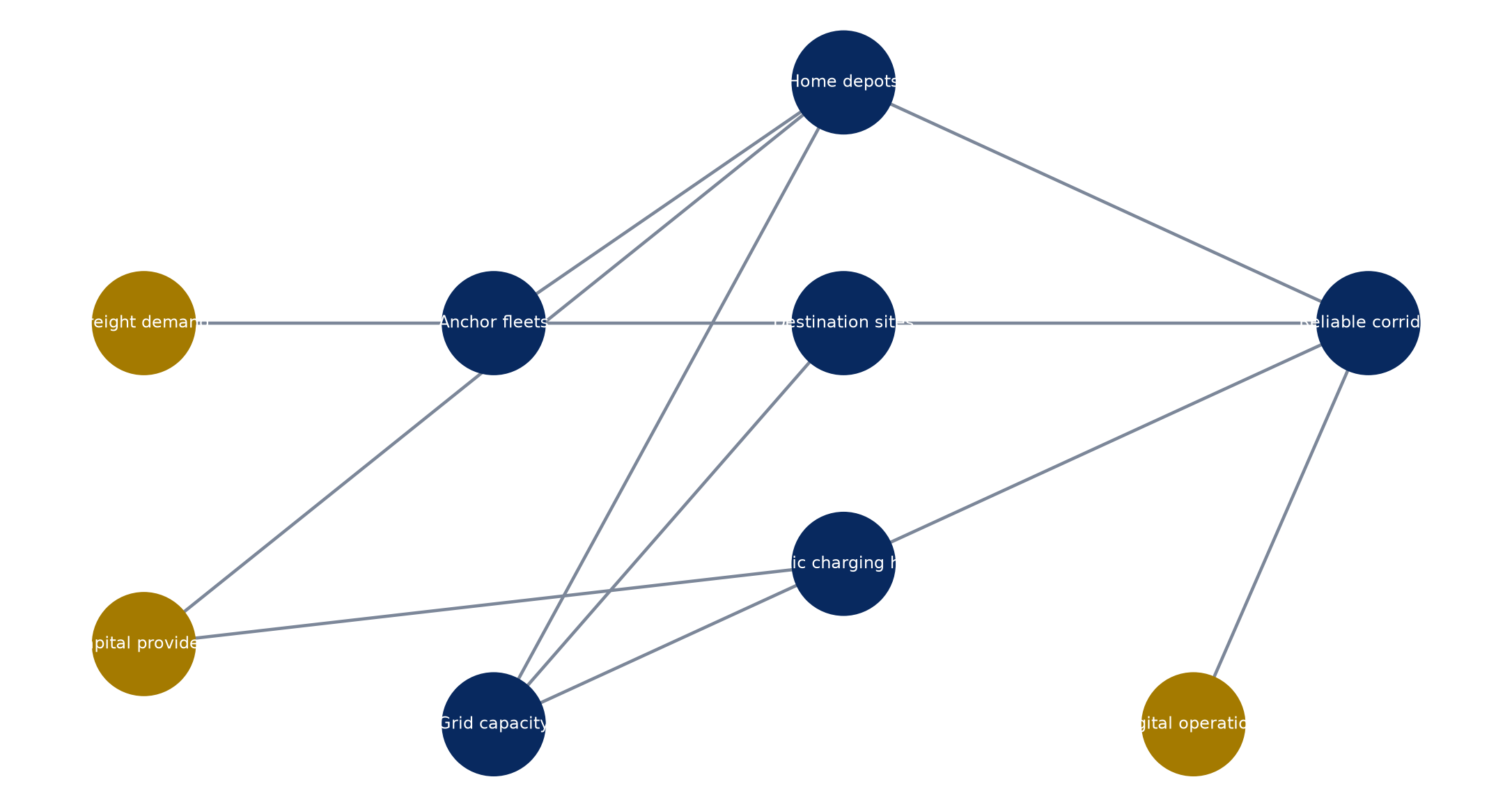
Proposed system map; actual ownership and operating responsibilities vary by corridor.
6. Select sites through a common admission test
Every candidate site should pass transport, land, grid, planning, technical, environmental and commercial tests. Transport criteria include route proximity, safe ingress and egress, turning geometry, queue storage, driver facilities and vehicle-class compatibility. Land criteria include tenure, expansion, drainage, fire access and restrictions on energy assets.
Grid criteria include available capacity, connection voltage, fault level, upgrade scope, energisation date and cost responsibility. Planning criteria cover zoning, permits, environmental review, community impacts and working-hour limitations. Commercial criteria include addressable demand, competition, tariffs, anchor commitments and alternative use.
Score evidence quality separately from site attractiveness. A promising location with an unverified connection date should not outrank a slightly weaker location that can be delivered. Admission should require minimum thresholds and named owners for every unresolved condition.
7. Treat grid capacity as a programme dependency
Heavy-duty charging can create concentrated multi-megawatt loads. NREL notes that stations serving several heavy trucks rapidly may require 20 MW or more, depending on design and duty cycle.[4] The power requirement can exceed the spare capacity at an otherwise attractive logistics site.
Engage the utility before final vehicle procurement or land commitment. Request a formal capacity study, upgrade scope, indicative cost, delivery sequence and constraints. Distinguish existing capacity, reserved capacity and capacity dependent on future network works. A preliminary map is useful for screening and insufficient for an investment decision.
The programme schedule should place utility studies, easements, substation work, transformers and energisation on the critical path. Each vehicle tranche should have a corresponding power tranche or credible interim plan.
8. Model the connection queue explicitly
Grid connection risk is both a timing risk and an allocation risk. Several projects may depend on the same feeder, substation or upstream reinforcement. A quoted date can change as other loads enter the queue or the project modifies its demand.
Maintain a connection register for every corridor node. Record application status, study stage, contracted capacity, security payments, milestones, dependencies, expiry and responsible party. Model delay cases at six, twelve and twenty-four months, then quantify idle assets, temporary charging costs, lost fleet savings and contract consequences.
Avoid paying for vehicles that cannot operate. Procurement agreements can align delivery slots with energisation evidence, while phased charger orders reduce stranded equipment. Sponsor support should cover delay costs that cannot be transferred.
9. Use managed charging before oversizing
Managed charging shifts and modulates load within route and dwell constraints. It can reduce connection capacity, demand charges and reinforcement needs. Its value depends on accurate schedules, charger communication, vehicle compatibility and an operating team able to manage exceptions.
Build an interval model of arrivals, required energy and departure deadlines. Optimise to the lowest feasible peak, then add operational reserve. Stress late arrivals, charger failure, cold weather, unexpected dispatch and partial software outage. The connection should support a resilient schedule rather than a theoretical optimum.
NREL depot data work shows that heavy-duty charging loads vary materially by vocation and parking schedule.[5] Corridor planning should therefore use vocation-specific profiles and preserve raw operating assumptions for utility review.
10. Decide where storage and on-site generation add value
Battery storage can shave peaks, provide limited resilience and allow a smaller grid connection. Solar can offset daytime energy at sites with suitable land or canopies. Neither resource creates energy independence unless its capacity, duration and operating constraints match the charging mission.
Evaluate storage against avoided connection cost, tariff savings, resilience value, degradation and replacement. Model the state of charge before the fleet peak. A battery used for price arbitrage may be unavailable during an outage. Define dispatch priority and minimum reserve.
Temporary generation can bridge a connection delay in limited cases. Include fuel logistics, emissions, permits, noise, operating cost and transition obligations. Treat it as a time-bound contingency with an approved exit date.
11. Size chargers from dwell and service requirements
Charger power should follow the energy needed within available dwell. Lower power can be economical at depots; high power is valuable where trucks must return quickly to service. Nameplate power is not delivered power when vehicles, cables, thermal conditions or shared power cabinets impose limits.
Model simultaneous sessions, power sharing, taper, connector occupancy and queue time. Include redundancy for the largest credible equipment outage. A site with ten chargers and one common transformer may have less resilience than its charger count suggests.
Specify acceptance tests at vehicle level. Commission each vehicle model across the power range, software interface and payment or reservation workflow. Record delivered energy, time, faults and recovery procedures.
12. Plan for megawatt charging selectively
Megawatt-class charging can support long-haul operations and short dwell, while increasing connection, cooling, safety and equipment requirements. The business case should identify the vehicles, routes and arrival windows that genuinely need it. Installing maximum power at every bay can destroy economics before utilisation develops.
Use a mixed-power site where demand is heterogeneous. High-power bays can serve time-critical long-haul vehicles, while lower-power bays serve regional vehicles, breaks or overflow. The control system should allocate power by departure deadline and paid service level.
Preserve physical space, ducts, switchgear pathways and grid expansion rights for later megawatt equipment. Phased readiness can retain future option value without funding idle hardware.
13. Design for truck movement and safety
Heavy vehicles require turning radii, clear heights, pavement strength, pull-through bays and queue storage that passenger-car sites often lack. Cables and dispensers should avoid conflict with trailers, refrigeration units and loading operations. Site design should accommodate emergency access and vehicle recovery.
Separate traffic, pedestrians and electrical equipment. Provide lighting, signage, driver facilities and safe waiting space. Review fire strategy, isolation, drainage and incident response with local authorities and insurers.
The IEA notes that only a small share of existing light-duty charging sites are practically accessible to trucks.[1] A corridor inventory should verify geometry and operations on site rather than classify suitability from charger power alone.
14. Define interoperability as an investment condition
Interoperability includes connector, communication, authentication, payment, reservation, roaming, data and maintenance compatibility. A technically compatible plug does not ensure a successful commercial session. Vehicle and charger software versions can affect performance.
Require standards-based interfaces and documented conformance tests. Preserve the ability to replace a network operator, payment provider or software platform. Data ownership and export rights should survive contract termination.
For public sites, provide transparent price display and access methods suitable for different fleet sizes. A small operator should not require a bespoke bilateral agreement to use essential corridor infrastructure. Contracted fleets can receive reserved capacity under rules that protect general access and emergency use.
15. Build a dependable reservation and queuing system
Truck charging consumes space and time. Unmanaged arrival peaks can create queues that disrupt driver hours and terminal appointments. Reservation systems should connect expected arrival, vehicle requirements, bay assignment, charging duration and contingency capacity.
Define priority rules before operations. These can recognise emergency vehicles, contracted capacity, delayed arrivals and vehicles approaching minimum state of charge. Publish cancellation and no-show terms. Protect the operator from speculative reservations while allowing reasonable schedule changes.
Physical queue design remains necessary because digital reservations cannot prevent traffic disruption during incidents. Measure arrival variance, waiting time, abandoned sessions and missed departure targets. Use these metrics to adjust capacity and pricing.
16. Set an uptime standard that reflects corridor dependence
Technical charger availability is only one measure. The service should be available to the required vehicle, at usable power, during the planned window, with functioning access and payment. Report successful session rate, delivered power, mean repair time and operational availability.
Corridor dependence raises the value of redundancy. Identify the consequence of each site outage and whether an alternative lies within practical range. Carry critical spares, remote diagnostics and maintenance coverage appropriate to the route.
Service contracts should link payments and credits to operating outcomes. Persistent failure can trigger replacement, step-in or operator substitution. A lender or public funder should receive the same performance data used by the operator.
17. Establish anchor demand without blocking the market
Anchor fleets can support early utilisation and provide route evidence. Their commitments may include minimum energy, capacity reservation, availability payments or site-development contributions. The contract should specify start date, ramp, vehicle compatibility, price, termination and remedies.
Avoid giving one anchor control over essential corridor capacity without an explicit policy decision. Reserve a defined share for other users, expansion and contingency. Concentration limits can protect the charging business from a single fleet failure.
Qualification should test the anchor's vehicle procurement, depot plan, route readiness and credit strength. A charging commitment without delivered trucks can still leave infrastructure idle. Link obligations to evidence and require periodic updates.
18. Construct a corridor demand ladder
Classify demand as contracted, capacity-reserved, fleet-approved, procurement-funded, qualified pipeline or policy aspiration. Apply different probability and timing to each category. Report the ladder by site, route and vehicle class.
The base case should rely on contracted and highly evidenced demand. Qualified pipeline can support expansion options. Policy aspiration can inform land and grid reservation while remaining outside debt sizing and near-term return projections.
Update the ladder quarterly. Remove fleets whose vehicle, route or funding assumptions no longer hold. Add new demand only after confirming charging compatibility and location. This discipline prevents duplicated demand across competing sites.
19. Stage capital around evidence
Divide the programme into development, enabling works, initial operating capacity and expansion. Development capital funds route analysis, site control, design, permits and utility studies. Enabling capital funds grid and civil works with long lead times. Initial capacity serves anchors. Expansion follows verified utilisation and additional contracts.
Each gate should have objective evidence. A development gate can require site option, utility response and anchor data. Construction can require permits, fixed-price contracts, committed equity and a connection agreement. Expansion can require operating history, service performance and contracted demand.
Stage gates reduce stranded capital while preserving schedule. They also reveal which party bears the cost of maintaining options before full commitment.
Table 1. Hypothetical corridor capital programme
| Use | Development | Initial build | Expansion | Total |
|---|---|---|---|---|
| Site control, design and permits | 8 | 3 | 2 | 13 |
| Grid connections and substations | 12 | 42 | 28 | 82 |
| Chargers and power equipment | 4 | 34 | 31 | 69 |
| Civil works and driver facilities | 5 | 24 | 15 | 44 |
| Software, commissioning and spares | 2 | 8 | 5 | 15 |
| Contingency and reserves | 4 | 14 | 9 | 27 |
| Total | 35 | 125 | 90 | 250 |
Wholly hypothetical; amounts are illustrative units and describe no identified corridor or financing.
20. Allocate development risk deliberately
Development risk includes unsuccessful sites, delayed permits, changing utility scope, land-option expiry and anchor withdrawal. It is rarely suitable for fully amortising project debt. Sponsor equity, public grants or risk-tolerant development capital should carry the earliest uncertainty.
Track development spend by site and decision gate. Stop weak sites quickly and preserve transferable work such as route data, design standards and utility studies. Avoid capitalising every failed option into the surviving sites without transparent approval.
Where a public authority funds development, define ownership and access to studies. Shared evidence can reduce duplication across utilities and site operators while protecting genuinely confidential fleet data.
21. Match financing to asset and demand maturity
Site control, grid assets, chargers and software have different lives and recovery values. Financing should match tenor, security and repayment to each asset and to the evidence supporting demand. Long-lived grid and civil works may support longer tenor after commissioning. Chargers may require faster amortisation and technology reserves.
Possible sources include sponsor equity, utility investment, public grants, infrastructure debt, equipment finance, vendor credit and anchor contributions. The capital structure should identify who controls the connection, land and equipment during operations and enforcement.
Debt sizing should rely on downside cash flow from operating sites. Undelivered expansion and speculative demand should remain outside the borrowing base until admission conditions are met.
22. Price electricity and service separately
The customer price can contain energy, network charges, demand recovery, reservation, parking, service and tax. Separate these elements so fleets can compare corridor charging with depot alternatives and so the operator can identify the source of margin.
Tariffs may vary by time, power, reservation and congestion. Dynamic prices should remain understandable and should not undermine route economics after fleets commit. Anchor contracts can use indexed formulas with collars, review rights and change-in-law provisions.
Model cost per delivered kilowatt-hour and cost per productive kilometre. Include losses, idle capacity, demand charges and unpaid queue time. A low energy purchase price does not create a viable service when connection and site costs remain unrecovered.
23. Protect smaller fleets and common access
Smaller operators may lack private depots, credit capacity or staff to develop charging. Public hubs can make electrification accessible if pricing, payment, reservations and vehicle access are practical. California's public-access blueprint work explicitly considers the risk that small businesses could be excluded during the transition.[6]
Set common-access rules and publish service standards. Consider credit support or pooled procurement rather than hidden cross-subsidy. A public contribution can be tied to measurable access, coverage or affordability outcomes.
Monitor user concentration and rejected demand. If contracted anchors occupy all useful capacity, the corridor may meet a private need while failing its public-network objective. Expansion triggers should respond to sustained unmet demand.
24. Coordinate depots and public hubs
Depot and public infrastructure should be planned as complements. Fleet depots absorb predictable base demand. Public hubs serve long routes, smaller fleets, exceptional days and resilience. Destination sites exploit operational dwell at ports, warehouses and terminals.
Model the effect of each new depot on public-site utilisation. Large fleets migrating demand behind the meter can weaken a public hub. Conversely, a delayed depot may create temporary public demand that disappears after energisation. Contracts and financing should distinguish durable from transitional use.
Create a shared corridor capacity view without exposing commercially sensitive dispatch data. Aggregated forecasts, connection status and commissioning dates can improve sequencing across fleets, utilities and site developers.
25. Design the corridor for expansion
Secure land, easements, ducts, switchgear space and utility rights for later phases. Oversize passive infrastructure where the marginal cost is justified. Delay rapidly changing charger hardware until demand is evidenced.
Expansion should preserve operations. Construction phasing, temporary traffic routes and electrical isolation should allow existing bays to remain available. Model the outage and revenue impact of each expansion method.
Standardise site modules where possible. Repeatable designs can reduce engineering time and support spare-parts consistency, while local grid, land and planning conditions still require site-specific diligence.
26. Build resilience beyond spare chargers
Resilience includes alternative sites, redundant power paths, storage, spare equipment, communications fallback, incident response and mutual support. A spare charger is insufficient when the common transformer, connection or access road fails.
Map single points of failure at site and corridor level. Test utility outage, communications loss, extreme weather, blocked access, equipment recall and sudden demand surge. Define minimum service and recovery time for each scenario.
Fleets should hold operational contingencies such as route reassignment, charging priority and minimum reserve. The corridor operator should coordinate information during disruption so vehicles do not converge on the same backup site.
27. Integrate cyber and data governance
Charging networks connect vehicles, chargers, energy controls, payment systems and fleet schedules. A cyber incident can interrupt service or expose commercially sensitive movement data. Security belongs in technical design, procurement and operations.
Define system boundaries, access control, patching, monitoring, incident response and supplier obligations. Maintain an offline or local operating mode for essential functions where feasible. Test recovery and preserve configuration backups.
Data governance should specify ownership, permitted use, retention, export and sharing. Utilities may need aggregated load data, while fleets may restrict route and customer information. Investment reporting should receive sufficient operating evidence without creating unnecessary exposure.
28. Procure for whole-life service
Evaluate equipment on delivered performance, interoperability, maintenance, warranty, upgrade path, cybersecurity, spares and supplier strength. Lowest purchase price can create higher downtime or replacement cost. Require evidence from comparable heavy-duty deployments.
Separate specifications that must remain common from elements that can vary by site. Common software and equipment can simplify operations while increasing correlated supplier risk. Preserve qualified alternatives and replacement rights.
Contracts should allocate design integration across charger, transformer, civil, software and utility scopes. Interface gaps are a frequent source of delay. A responsible integrator should own the complete acceptance test.
29. Create an integrated programme office
The corridor requires coordinated decisions across fleets, utilities, landowners, public authorities, technology providers, financiers and operators. Establish a programme office with defined decision rights, schedule ownership and issue escalation.
Maintain a single dependency register covering fleet orders, sites, permits, utility works, equipment, civil construction, commissioning and operating contracts. Report the critical path and the effect of delay on connected corridor coverage.
Governance should separate commercial confidentiality from programme facts. Parties can share milestone status, capacity ranges and risks without disclosing customer contracts or proprietary models. Independent technical assurance can support investment gates.
30. Sequence construction around the minimum viable corridor
The first build should create a usable route for identified fleets rather than distribute isolated assets widely. Define the minimum viable corridor by origin, destination, depot, necessary en-route sites and backup coverage. Commission it end to end.
Later phases can add routes, capacity and redundancy. A phased US strategy similarly begins with freight hubs and priority corridors before national coverage.[3] The principle applies across geographies even when specific policy and network conditions differ.
Use a coverage test for each phase. A site is counted only when energised, commissioned, accessible, digitally integrated and supported. Planned or partly built capacity should remain outside operating coverage.
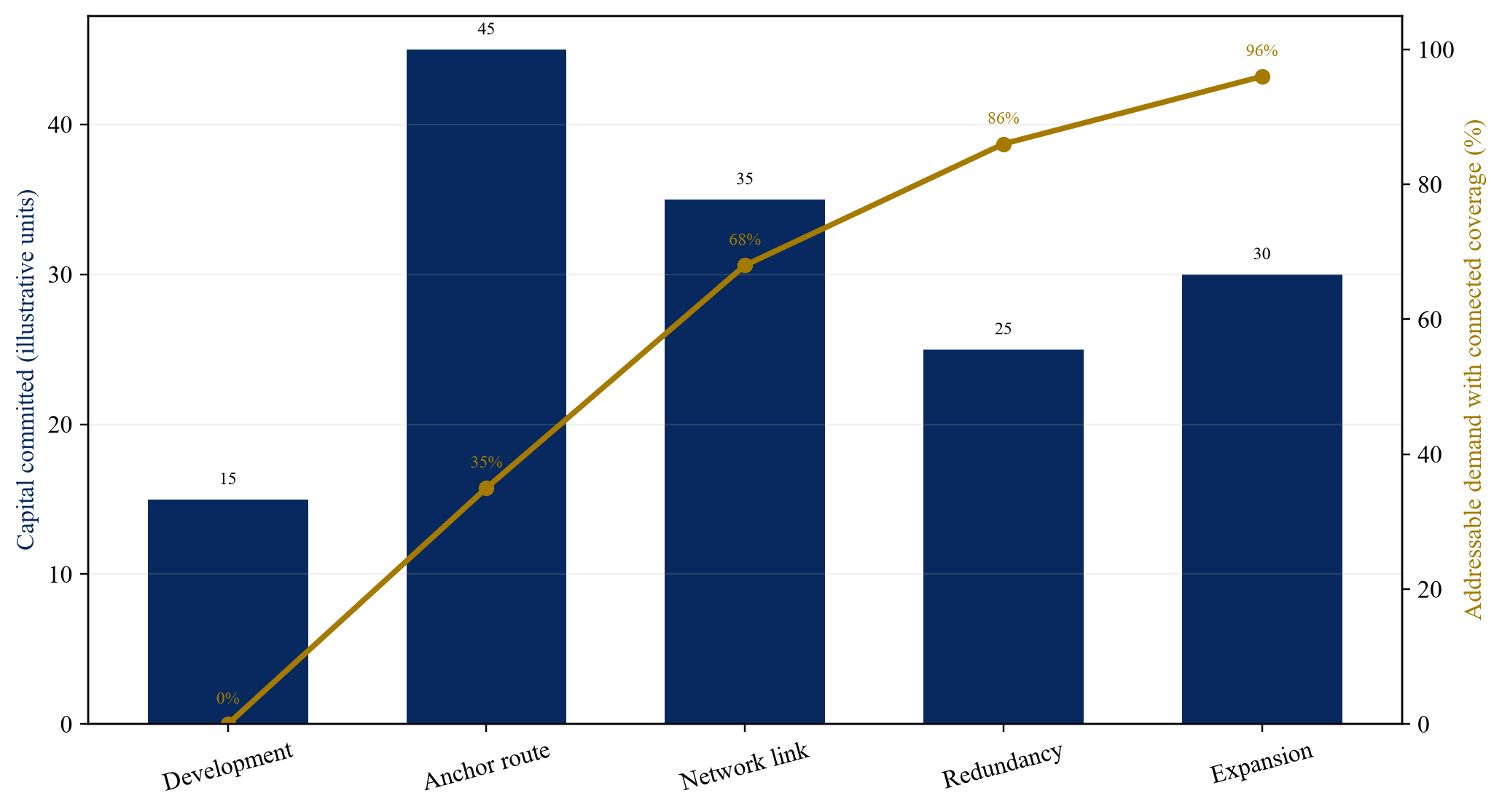
Wholly hypothetical; values illustrate staging logic and describe no identified corridor.
31. Model utilisation as a ramp
New charging assets rarely begin at mature utilisation. Model vehicles entering service by fleet, route and month. Include procurement delay, driver training, depot readiness and customer ramp. Separate energy throughput from occupied time and reserved capacity.
Low utilisation can produce high unit cost because connection, land and maintenance costs are largely fixed. High utilisation can create queues and lost service. The investment case should identify the economic operating band and the expansion lead time required before congestion.
Use trigger-based expansion. Sustained throughput, reservation rejection or anchor commitment can start the next phase. Avoid building solely on a single peak month or a non-binding forecast.
32. Test capex and operating sensitivities together
Capital risk includes grid scope, land works, civil quantities, equipment price and delay. Operating risk includes utilisation, energy cost, demand charges, maintenance, rent, insurance and downtime. These risks interact: delay raises interest and can defer anchor contracts; low utilisation increases cost per unit and weakens maintenance coverage.
Build cases around the variables management can observe and influence. Show the break-even throughput, minimum contracted demand and maximum affordable connection cost. Preserve a separate contingency for unresolved grid and ground conditions.
Do not offset capex overrun with uncontracted utilisation growth. Each mitigation should have an owner, evidence and deadline.
Table 2. Hypothetical corridor operating sensitivities
| Metric | Base case | Downside | Severe case | Management response |
|---|---|---|---|---|
| Year-three energy throughput | 100 | 78 | 58 | defer expansion and secure anchors |
| Average realised service price | 0.42 | 0.38 | 0.34 | revise mix and index contracts |
| Delivered electricity cost | 0.16 | 0.21 | 0.28 | tariff redesign and managed charging |
| Operational availability | 98% | 94% | 88% | spares, service credits and replacement |
| Grid energisation delay | 0 months | 9 months | 18 months | stage vehicles and invoke support |
| Construction cost overrun | 4% | 14% | 25% | contingency, scope gate and equity cure |
| Peak queue time | 12 min | 35 min | 70 min | reservations and accelerated capacity |
Wholly hypothetical; figures describe no identified company, corridor or tariff.
33. Allocate risks to the party able to control them
The fleet controls route deployment, vehicle arrival and some charging behaviour. The site operator controls access, charger availability and customer service. The utility controls defined connection work and network operation. Contractors control design and construction within their scope. Government controls permits and policy through established processes.
Allocate each risk through obligations, evidence, remedies and limits. A risk label without a remedy does not transfer risk. Check counterparty credit and insurance. Retained risks require contingency or return.
Interface risks need special treatment because several parties may contribute. Assign an integrator, require coordinated testing and prevent suppliers from disclaiming the complete system outcome.
Table 3. Heavy-EV corridor risk-allocation matrix
| Risk | Primary controller | Required evidence | Contract control | Investor protection |
|---|---|---|---|---|
| Fleet demand | Fleet and anchor customer | routes, vehicle orders, commitments | minimum use or reservation | phased capital and concentration limits |
| Grid connection | Utility and site sponsor | study, agreement, milestones | dates, contributions, change control | draw conditions and long-stop support |
| Site delivery | Developer and contractor | permits, design, programme | fixed scope, delay and completion terms | contingency and independent certification |
| Charger performance | Supplier and operator | tests, references, telemetry | warranty, uptime and replacement | holdback, reserve and step-in |
| Energy price | Operator and fleet | tariff and forecast | indexation, pass-through and collars | downside covenant and liquidity |
| Interoperability | Integrator and suppliers | conformance and vehicle tests | open interfaces and cure | replacement and data portability |
| Corridor outage | Operator and programme office | resilience study and drills | response and mutual support | redundancy and insurance |
Proposed allocation principles; contracts and law determine actual rights and obligations.
34. Measure network value
Site-level revenue misses corridor value. A new node can unlock routes, increase confidence in neighbouring sites, provide backup and enable smaller fleets to electrify. Measure connected origin-destination coverage, practical route kilometres, reachable freight volume and resilience.
Avoid double counting. The same vehicle may appear in several site forecasts, while a single charging event can support only one trip at a time. Build demand from unique fleet missions and reconcile across the network.
Public support may be justified by coverage, interoperability or access outcomes that private revenue cannot capture. Define these outcomes before funding and verify them after commissioning.
35. Establish performance covenants
Operating covenants can track energised capacity, successful sessions, delivered power, uptime, queue time, anchor concentration, contracted demand, liquidity and debt-service coverage. Construction covenants can track permits, utility milestones, budget, contingency and completion.
Set thresholds that trigger graduated action. Early warning can require a plan; sustained underperformance can stop expansion or distributions; severe failure can require equity, replacement or step-in. Avoid covenants that encourage the operator to deny low-margin users or conceal outages.
Data should reconcile charger telemetry, utility meters, invoices, reservations and maintenance records. Independent review is appropriate where public support or lender reliance is material.
36. Plan the downside before construction
Downside planning should identify which assets can be redeployed, which site rights retain value, and how service continues during restructuring. Chargers may be movable; grid connections and civil works are site-specific. Software and customer contracts may depend on the operator.
Define step-in rights, data access, spare ownership, maintenance continuity and assignment. Preserve land tenure long enough for a replacement operator. Confirm whether permits, utility agreements and grants survive a change of control.
The strongest recovery plan keeps an essential corridor operating. Liquidation value alone may be weak when equipment is specialised or removal is costly. Continuity can preserve revenue, public outcomes and asset value.
37. Use insurance as a defined layer
Insurance can address construction damage, property, equipment breakdown, cyber events, liability, business interruption and environmental exposures. It does not replace sound design, maintenance or redundancy. Review exclusions for batteries, high-voltage equipment and emerging technology.
Match insured values and interruption periods to replacement lead times. A transformer or specialised charger can take longer to replace than a standard policy assumption. Coordinate claims responsibility across landlord, utility, operator and contractor.
Retained deductibles and uninsured delay require reserves or sponsor support. Record insurance renewals and material exclusions as programme risks.
38. Integrate permitting and community impacts
Corridor sites can affect traffic, noise, lighting, land use and local distribution networks. Engage planning authorities and communities early, particularly near ports, warehouses and residential areas. Design mitigations into layout and operating hours.
Permitting schedules should include environmental, building, electrical, fire, access and highway approvals. Identify sequential dependencies and appeal risk. A generic allowance is insufficient when a site is on the critical path.
Track local benefits such as cleaner freight operations, access for smaller fleets and workforce development without presenting estimated benefits as observed outcomes. Define the measurement method before publication or funding claims.
39. Develop the workforce and operating model
Heavy-duty charging requires high-voltage technicians, civil and electrical contractors, software support, site attendants, fleet dispatchers and emergency responders. Workforce constraints can delay commissioning or lengthen outages.
Plan training, certification, shift coverage and supplier support. Specify which functions are in-house and outsourced. A corridor with several sites may justify a shared maintenance team and spare inventory.
Operations manuals should cover normal charging, reservations, queue control, isolation, fire response, cyber incident, grid outage and vehicle incompatibility. Conduct drills before commercial opening.
40. Apply a corridor investment-committee test
The committee should receive one integrated pack: freight evidence, route feasibility, site ranking, grid status, technical design, anchor contracts, capex, operating model, financing, risks and phased roadmap. Reconcile assumptions across all models.
Approval should answer five questions. Is there evidenced demand? Does the initial phase create a usable route? Can the grid and sites be delivered before vehicles require them? Are service and interoperability dependable? Can downside be contained without relying on speculative growth?
Conditions should follow unresolved evidence. A committee can approve development, enabling works or full construction separately. The decision record should state what new evidence permits the next commitment.
41. Implementation roadmap
During the first ninety days, establish governance, gather fleet data, map routes, screen sites and start utility engagement. Produce a demand ladder and connection register. Secure options on priority sites without committing full construction capital.
During months four to nine, complete technical and commercial studies, negotiate anchor terms, progress permits, fix interfaces and select the minimum viable corridor. Confirm capital sources and risk allocation. Test vehicle-charger compatibility.
During months ten to twenty-four, construct the first operating route, commission it end to end and collect performance data. Expand only after demand, service and grid evidence meet approved triggers. Update the roadmap as technology and policy change.
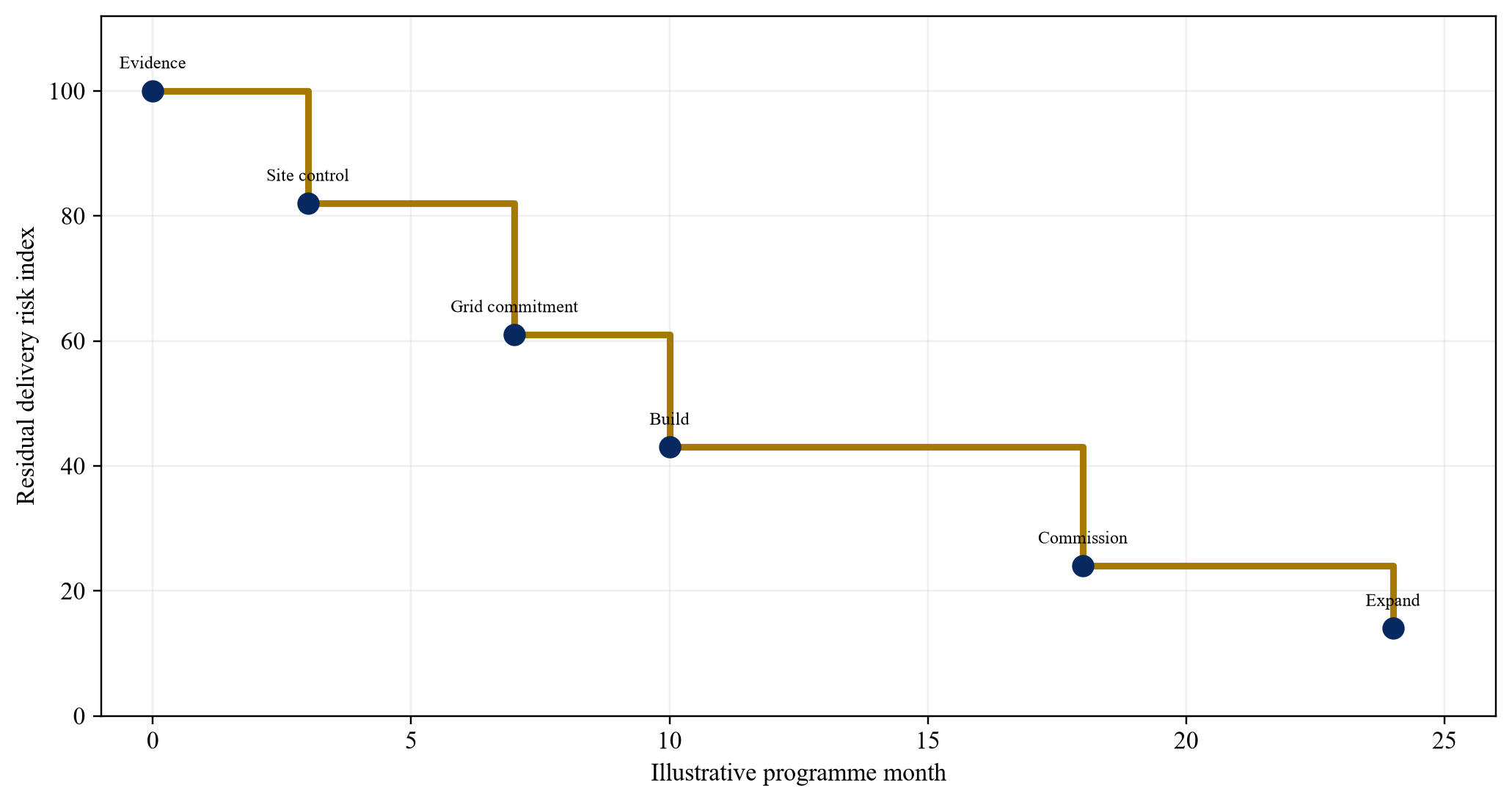
Proposed roadmap; timing depends on site, utility, procurement and permitting conditions.
42. Limitations
The framework is general and does not replace route engineering, grid studies, legal diligence, environmental review, tax analysis or regulated-tariff advice. Vehicle performance, charger standards, policy and equipment costs can change. Site-specific evidence should govern every commitment.
The numerical exhibits are hypothetical. They describe no identified corridor, operator, fleet, utility or financing. They should not be used as forecasts, valuation inputs or benchmarks without independent verification and adaptation.
Public evidence is uneven across geographies. The cited US, European and international sources illustrate planning methods and market development. Local law, grid structure, freight patterns and commercial practice determine application elsewhere.
43. Conclusion
Heavy-EV corridors become investable when freight demand, vehicle capability, land, charging and grid capacity mature together. The first objective is a connected and dependable operating route for evidenced fleets. Charger count and announced capacity are weak substitutes for end-to-end service.
The programme should begin with route and dwell data, classify the electrifiable fleet, admit sites through common tests and put grid dependencies on the critical path. Depot charging should carry predictable base demand, while public and opportunity sites extend routes, support smaller fleets and create resilience.
Staged capital, anchor commitments, open interfaces, performance-linked contracts and transparent operating data can contain early uncertainty. Expansion should follow observed throughput and qualified demand. The result is a corridor built before the trucks require it, with enough discipline to avoid building too much, too early or in the wrong place.
Appendix A Investment-committee questions
1. Which freight missions define the corridor and what evidence supports them?
2. Which routes are feasible under conservative vehicle and weather assumptions?
3. Which charging events occur at depots, destinations and public hubs?
4. Does the first phase create a complete operating route?
5. Which sites pass transport, land, grid, permit and commercial tests?
6. What capacity is available, reserved and dependent on future grid work?
7. How do vehicle delivery, energisation and commissioning dates align?
8. Which fleets have binding or evidenced demand commitments?
9. What share of demand depends on one customer, site or vehicle model?
10. How are smaller fleets and common access addressed?
11. What power, connector and interoperability tests have been completed?
12. What happens when the critical site or connection fails?
13. Which capital is committed at each decision gate?
14. How do capex, energy cost, utilisation and uptime interact?
15. Which risks remain with the sponsor and how are they funded?
16. What permits, land rights and community conditions remain unresolved?
17. Can a replacement operator access the site, data and equipment?
18. Which metrics trigger remediation, expansion or a stop?
References
- International Energy Agency, Global EV Outlook 2026: Electric Vehicle Charging, 2026. https://www.iea.org/reports/global-ev-outlook-2026/electric-vehicle-charging-chap-6-and-10
- European Union, Regulation (EU) 2023/1804 on the deployment of alternative fuels infrastructure, consolidated text accessed 2 October 2026. https://eur-lex.europa.eu/eli/reg/2023/1804/2026-01-08/eng
- US Department of Energy, US Department of Transportation and US Environmental Protection Agency, National Zero-Emission Freight Corridor Strategy, 2024. https://afdc.energy.gov/files/u/publication/zef-corridor-strategy.pdf
- National Renewable Energy Laboratory, The Dawn of Electric Trucking Calls for High-Power Charging, 2025. https://www.nrel.gov/news/features/2025/the-dawn-of-electric-trucking-calls-for-high-power-charging
- National Renewable Energy Laboratory, Depot-Based Vehicle Data for National Analysis of Medium- and Heavy-Duty Electric Vehicle Charging, 2024. https://www.nrel.gov/docs/fy24osti/88241.pdf
- California Energy Commission, STC Traffic Equity-Driven Public Access ZEV Charging Blueprint, 2026. https://www.energy.ca.gov/publications/2026/stc-traffic-equity-driven-public-access-zev-charging-blueprint
- California Energy Commission, An Investment Blueprint for Heavy Duty Charging to Support Battery-Electric Drayage along the Interstate 710 Corridor, 2025. https://www.energy.ca.gov/publications/2025/investment-blueprint-heavy-duty-charging-support-battery-electric-drayage-along
- California Energy Commission, Going for Gold: A Blueprint to Catalyze Medium- and Heavy-Duty Charging Infrastructure Investments in the Los Angeles Region Preceding the 2028 Games, 2026. https://www.energy.ca.gov/publications/2026/going-gold-blueprint-catalyze-medium-and-heavy-duty-charging-infrastructure
- California Energy Commission, A Replicable Infrastructure Blueprint for Zero-Emission Medium- and Heavy-Duty Vehicles in the South Coast Air Basin, 2026. https://www.energy.ca.gov/publications/2026/replicable-infrastructure-blueprint-zero-emission-medium-and-heavy-duty-vehicles
- California Energy Commission, Developing a MDHD ZEV Infrastructure Blueprint for the South Coast, 2026. https://www.energy.ca.gov/publications/2026/developing-mdhd-zev-infrastructure-blueprint-south-coast
- California Energy Commission, Assembly Bill 2127 Second Electric Vehicle Charging Infrastructure Assessment, 2024. https://www.energy.ca.gov/publications/2024/assembly-bill-2127-second-electric-vehicle-charging-infrastructure-assessment
- National Renewable Energy Laboratory, EVI-X Modeling Suite of Electric Vehicle Charging Infrastructure Analysis Tools, accessed 2 October 2026. https://www.nrel.gov/transportation/evi-x.html
- US Department of Transportation, An Action Plan for Medium- and Heavy-Duty Vehicle Energy and Emissions Innovation, 2024. https://www.transportation.gov/sites/dot.gov/files/2024-12/MHDV%20Plan.pdf
- California Energy Commission, 2024 Zero-Emission Vehicle Infrastructure Plan: Deployment Strategy 2025 to 2030, 2025. https://www.energy.ca.gov/publications/2025/2024-zero-emission-vehicle-infrastructure-plan-deployment-strategy-2025-2030
About the Author
Authored by Chennakeshav Adya Independent Researcher
Chennakeshav (CK) is a corporate finance and investment banking executive with 25+ years of global experience in deal origination, structuring and execution across M&A, growth capital and corporate strategy. He has led value-creation mandates for founders, corporates and funds — bridging the boardroom view to hands-on execution and close.
His career spans Morgan Stanley, HSBC, Lloyds Banking Group, EWEC, ADQ portfolio companies and Emirates Growth Fund, across TMT, real estate, fintech, deeptech, cleantech, infrastructure and energy. He has partnered with C-suite leaders, private equity and venture funds, sovereign wealth funds and family offices to finance complex fund raises and scale-up ventures, and has led M&A due diligence, post-merger integration and business-transformation initiatives to create value.
At Matchpoint Partners he is Managing Partner, leading the firm's corporate finance, M&A and capital-raising practice. He holds an MBA from London Business School, an engineering degree from VTU and a Master of Laws (LLM, in progress) from UCL London.
An active start-up mentor, CK mentors at Techstars, DIFC FinTech Hive, Startup Grind, Founder Institute and IN5, serves as Entrepreneur Mentor in Residence (EMiR) at London Business School, and judges the Entrepreneurship World Cup.
Matchpoint profile: https://www.matchpoint-partners.com/team/ck-adya.html LinkedIn: https://www.linkedin.com/in/ckadya/
