
Introduction
Computing in orbit can create value where data originates in space, where immediate processing reduces downlink volume, where latency to another spacecraft matters, or where isolated infrastructure has strategic utility. ESA has documented onboard edge-computing applications that filter cloud-covered imagery, extract features and support low-latency Earth-observation products. NASA's High Performance Spaceflight Computing programme addresses autonomy, artificial intelligence, signal processing, data management and fault tolerance under radiation and power constraints. These examples support the technical relevance of onboard computing. They do not establish the economics of a large commercial orbital data centre. [3][5][6]
An investor therefore needs a decision system that preserves upside while limiting irreversible capital before the evidence is mature. The analysis must connect regulatory status, orbital design, spacecraft mass, usable power, thermal rejection, compute performance, connectivity, launch cadence, failure probability, customer acceptance and replenishment. A valuation that omits any of these links can assign value to capacity that never becomes billable.
1. Define the investment decision
State the decision precisely: fund a technology demonstration, finance a first commercial cluster, acquire an operating platform, provide growth capital for a constellation, or underwrite project debt against contracted service. Each decision has a different evidence threshold and risk allocation.
Define the maximum capital at risk before the next objective milestone. Specify which findings permit investment, repricing, a smaller tranche, technical redesign, deferral or withdrawal. The investment committee should know which uncertainties can be resolved with money and time and which depend on external authorization, launch access or unproven physics.
Separate strategic optionality from base-case value. Access to orbital compute may support national resilience, Earth-observation analytics or future in-space services. These possibilities can justify an option budget. They should not be entered as contracted revenue without executed commitments and demonstrated delivery.
2. Establish the valuation perimeter
List the legal entities, intellectual property, spacecraft buses, payload designs, software, ground systems, spectrum rights, launch contracts, customer agreements, supplier arrangements, personnel and insurance included in the valuation. Identify assets owned, licensed, leased, hosted or shared with affiliates.
Define the unit of capacity. Installed accelerator nameplate, usable compute load, delivered workload, accepted service and collected revenue are different states. The valuation model should distinguish planned nodes, manufactured nodes, launched nodes, deployed nodes, commissioned nodes, service-available nodes and billable nodes.
Identify dependencies outside the perimeter. A platform may depend on another constellation for optical relay, a launch provider for cadence, a ground-station network for command and control, a cloud provider for orchestration, or a sovereign customer for demand. Price and contract these dependencies before treating the platform as standalone.
3. Separate evidence from scenarios
Create an evidence register for every material valuation input. Regulatory filings, executed contracts, test reports, bills of material, thermal-vacuum results, radiation tests, launch reservations, insurance indications and bank records provide stronger support than presentations or non-binding discussions.
Label every future input as a management scenario until independently supported. Proposed satellite counts in an application indicate requested scope and do not prove deployment. Published technical targets indicate design intent and do not prove performance. A customer memorandum indicates interest and does not prove minimum revenue.
Assign confidence levels and expiry dates. Launch pricing, component availability, spectrum coordination and customer requirements can change before deployment. The model should identify inputs that require refresh at each capital gate.
4. Read regulatory filings as constraints
Review the complete application, technical attachment, waiver requests, public comments, coordination record and subsequent orders. The February 2026 FCC notice states that the SpaceX application seeks authority for a system at 500 to 2,000 kilometres using optical inter-satellite links and specified radio-frequency links. The notice also states that the application was accepted for filing and opened for comment. This procedural status must not be treated as authorization. [1]
Map requested shells, inclinations, frequencies, gateways, telemetry links, maneuver capability and disposal plan. Test whether the commercial model depends on every requested element or can begin with a smaller authorized configuration.
Record conditions that could reduce capacity, delay service or add cost. Spectrum coordination, collision avoidance, astronomy, debris mitigation, re-entry safety, national security and earth-station licensing may affect design and timetable. Obtain specialist advice for each relevant jurisdiction.
5. Define the service and paying customer
Specify the workload that gains measurable value from orbital execution. Candidate workloads include onboard image processing, sensor fusion, autonomous operations, data compression, secure inter-satellite analytics and time-sensitive space-domain services. General-purpose terrestrial cloud replacement requires a separate economic case.
For each workload, identify data source, compute requirement, storage, model update process, output route, latency requirement, security classification, service level, acceptance test, invoice basis and customer budget. The service must be deliverable through the planned orbital and ground architecture.
Distinguish reserved capacity, take-or-pay minimums, usage-based revenue, development fees and government milestone payments. Value contracted minimums separately from discretionary usage. Test termination rights, appropriations risk, launch-delay relief and liability caps.
6. Build the capacity-state ladder
Begin with planned electrical power and compute hardware. Deduct power conversion, communications, guidance, thermal control, storage, fault tolerance and housekeeping loads. Apply eclipse, degradation, pointing and contingency limits to derive usable compute power.
Convert usable power into workload-specific throughput using tested hardware and software. Deduct redundancy, unavailable nodes, maintenance mode, radiation events, communication windows and orchestration overhead. The resulting service-available capacity can then be compared with customer acceptance and billing records.
Maintain a reconciliation from planned megawatts to collected cash. An investor should be able to trace every step and identify which party certifies it.
7. Model launch mass and delivered cost
Create a mass budget for structure, shielding, solar arrays, batteries, power electronics, compute, storage, thermal hardware, communications, propulsion, guidance, harness, deployment mechanisms and margin. Reconcile the mass budget to design drawings and supplier data.
Separate advertised launch price from delivered cost. Delivered cost can include integration, dispenser, separation system, testing, transport, range, licensing, mission assurance, insurance, schedule reserve and orbital transfer. Rideshare and dedicated missions also create different timing and orbit-selection consequences.
Model cost per successfully commissioned kilogram and cost per service-available kilowatt. These measures incorporate launch failure, deployment failure and early-life anomalies. They provide a more useful valuation input than launch price per kilogram alone.
8. Test launch cadence and concentration
Build a manifest by node, payload mass, orbit, provider, vehicle, integration date, regulatory dependency and contractual slot. Test whether annual deployment and replacement demand can be met without relying on a single uncontracted cadence assumption.
The United States Space Force reported 144 launches across its eastern and western ranges in 2024 and described higher cadence as an operational objective. This demonstrates range activity, while providing no assurance of commercial capacity for a particular programme. [14]
Stress launch delays, shared-ride displacement, vehicle stand-down, range closure, payload requalification and late supplier delivery. Quantify revenue delay, storage cost, workforce retention and replacement backlog under each case.
9. Evaluate orbital architecture
Map altitude, inclination, local time of ascending node, coverage, eclipse, radiation environment, conjunction exposure, communication geometry and disposal route. Different shells can change power generation, latency, ground visibility, thermal cycling and replenishment.
Avoid treating altitude as a single optimization variable. A lower orbit may reduce propagation distance and improve natural decay while increasing drag and replenishment needs. A higher orbit may improve persistence and coverage while changing radiation and disposal exposure.
Model the service as a time-varying network. Customer access, inter-satellite routes and ground connectivity depend on constellation geometry, link availability, weather and traffic. Use validated orbital simulation before committing revenue to aggregate node count.
10. Build the power model
NASA's small-spacecraft technology review states that solar generation is the predominant energy source for small spacecraft and discusses angle of incidence, eclipse, degradation, batteries and power management. Use the current design and mission orbit rather than a generic solar constant to establish available energy. [7][8]
Model solar-array output by orientation, temperature, age, radiation degradation, shadowing and deployment tolerance. Model battery depth of discharge, cycle life, reserve policy and end-of-life capacity. Include conversion losses and distribution limits.
Set a service-available power envelope. Compute scheduling should respect housekeeping and contingency reserves. Revenue should depend on energy that can be delivered repeatedly within component temperature and battery-life limits.
11. Convert power into compute
Measure workload throughput per watt on representative hardware under relevant fault-tolerance, encryption and software conditions. Laboratory benchmark results should include memory, storage, network and orchestration overhead rather than accelerator performance alone.
Radiation-hardened processors can differ from terrestrial hardware in performance, energy efficiency, availability and cost. NASA describes HPSC as a radiation-tolerant multicore architecture with power-management, fault-tolerance and connectivity objectives. Its 2026 testing status is evidence of programme progress and does not establish commercial orbital data-centre performance. [3][4]
Model hardware refresh carefully. A new terrestrial accelerator generation cannot be assumed to enter the orbital fleet immediately. Qualification, redesign, shielding, software validation, procurement and launch may create a multi-year lag.
12. Model thermal rejection
In vacuum, spacecraft reject heat primarily through radiation. NASA's thermal-control guidance explains that limited surface area, low thermal mass, power density and competing uses for external area constrain small spacecraft thermal design. [8][9]
Build a steady-state and transient thermal model for sunlit and eclipse periods, compute duty cycle, communications, battery charging and safe mode. Include radiator orientation, emissivity degradation, conductive paths, heat pipes, pumps if used and component temperature limits.
Translate thermal limits into service capacity. If sustained compute must be throttled to remain within temperature, the valuation should use thermally deliverable throughput. Require thermal-vacuum tests, model correlation and in-orbit telemetry before releasing large deployment capital.
13. Quantify radiator and structure trade-offs
Estimate radiator area and mass for the target heat load and temperature. Higher rejection temperature can reduce required area while placing stricter demands on electronics and reliability. Deployable radiators may increase area and introduce mechanisms, pointing constraints and failure modes.
Map structural and launch loads. The compute payload, arrays and radiators must survive vibration, acoustic load and deployment. Additional shielding or thermal hardware increases mass and launch cost and may reduce payload fraction.
Use an integrated mass, power and thermal model. Independent assumptions can produce an impossible design in which compute power, radiator area and launch mass each fit separately and fail when combined.
14. Price radiation and fault tolerance
NASA and ESA describe total ionizing dose, single-event effects, memory errors and permanent component damage as core space-computing constraints. Mitigations include shielding, radiation-tolerant components, error correction, redundancy and recovery software. [3][6][10]
Model degradation and failure at component, node and constellation levels. Separate recoverable software errors, degraded capacity, loss of a compute module and total node loss. Include common-mode vulnerabilities such as a component defect or software update.
Translate fault tolerance into cost and revenue. Redundant compute consumes mass, power and capital while supporting service availability. The valuation should recognize the net effect rather than treating redundancy as free capacity.
15. Evaluate communications and optical links
Map workload input, intermediate transfers, model updates, command and control, output and billing evidence across optical and radio links. Record bandwidth, acquisition time, pointing accuracy, link availability, protocol overhead and alternate paths.
Optical inter-satellite links can support high-capacity paths without making the network independent of ground gateways or radio authorization. Cloud, atmospheric conditions, gateway geography and route congestion can affect space-to-ground delivery.
Price the network dependency. If the orbital data centre relies on a third-party constellation, obtain capacity, priority, interoperability, security, term, change-of-control and failure provisions. A technical interface without enforceable service rights is not bankable connectivity.
16. Test latency by complete path
Calculate propagation, routing, queue, compute and application-response time. A simple altitude divided by the speed of light is only one component. Inter-satellite hops, gateway routes, encryption and workload scheduling can dominate end-to-end performance.
Compare the orbital route with terrestrial fibre, cloud and edge alternatives for each customer. Value exists where the orbital path changes an operational outcome, data-transfer cost or mission response. A modest latency improvement without customer economics should not support a premium.
Use measured demonstrations. Record percentile latency, availability, jitter and data completeness under representative geometry and load.
17. Assess storage and data durability
Define data classes, retention periods, redundancy, encryption, jurisdiction, deletion and recovery. Storage media in radiation environments require error detection, correction, scrubbing and lifecycle management.
Model write endurance, degradation, capacity reserve and recovery after node loss. Determine whether data can be recreated from source sensors or must be replicated across nodes or returned to Earth.
Link durability obligations to service contracts and liability. A customer may value rapid processing while still requiring authoritative archives on Earth. The cost model should include every required copy and transfer.
18. Build cyber and command-control diligence
Map identities, keys, software supply chain, update process, command authority, ground stations, crosslinks, customer interfaces and incident response. A compromised command path can affect the whole constellation.
Require secure boot, signed updates, hardware roots of trust, segmented control, key rotation, logging and recovery appropriate to the mission. Test loss of ground contact, corrupted updates and malicious workload behavior.
Value cyber controls through avoided service loss, regulatory exposure and recovery cost. Obtain independent testing and evidence. Policy descriptions alone do not establish operating effectiveness.
19. Model useful life and degradation
Set component-level life assumptions for solar arrays, batteries, processors, memory, storage, communications, propulsion and mechanisms. Define the limiting component and the conditions that determine end of service.
GAO reported that a proliferated US defence architecture expected satellite replacement roughly every five years. That programme is not a commercial orbital data-centre benchmark. It demonstrates that replenishment can be a defining lifecycle assumption in large low-Earth-orbit systems. [15]
Build survival curves rather than one retirement date. Include early failures, gradual degradation and common-mode events. Update the curve as flight data accumulates.
20. Construct the replacement cycle
For a steady 40-node constellation with a five-year useful life, the simple long-run replacement requirement is eight nodes per year before additional failures or growth. A delayed replacement year creates a backlog and can reduce billable capacity.
Schedule design freeze, procurement, manufacturing, testing, launch integration, licensing, launch and commissioning backward from required service entry. A replacement reserve should fund the whole delivered cycle, including unsuccessful deployments and working capital.
Model technology generations separately. Replacement can improve compute efficiency, while interface changes can create software and spares complexity. Do not assume each new generation arrives on time or at lower delivered cost.
21. Address disposal and debris obligations
NASA identifies orbital debris as a safety and mission-assurance discipline and maintains requirements for assessment, mitigation and end-of-mission planning. FCC licensing also examines debris mitigation for commercial systems. [16][17][18]
Include propulsion reserve, tracking, conjunction assessment, collision-avoidance operations, passivation, disposal reliability and re-entry analysis. Estimate the cash and capacity consequences of holding fuel for disposal and maneuvers.
Treat disposal compliance as a continuing operating obligation. A large constellation can face changing requirements, coordination demands and public scrutiny. Use legal and technical specialists and preserve contingency for design changes.
22. Map spectrum and coordination risk
Identify every frequency, link direction, bandwidth, earth station, gateway, telemetry function and jurisdiction. Record domestic authorization, International Telecommunication Union coordination, national landing rights and shared-band constraints.
Build a schedule for filings, comments, coordination, testing and operational conditions. Distinguish requested frequencies from authorized and coordinated use. A business case dependent on contested or incomplete rights requires an explicit probability and timetable.
Test alternative architectures. Optical links may reduce some radio demand while introducing acquisition and weather dependencies. Backup telemetry may remain essential.
23. Evaluate manufacturing repeatability
Review engineering models, qualification units, flight units, supplier capacity, yields, rework, test duration and configuration control. A successful prototype does not prove a repeatable production system.
Reconcile the bill of materials to purchase orders, lead times and export controls. Identify sole-source processors, memory, solar cells, batteries, optical terminals, radiation components and deployment mechanisms.
Build learning curves only from relevant evidence. Include quality cost, acceptance-test failures and redesign. Set capital releases against units that pass defined factory and environmental tests.
24. Establish launch and in-orbit insurance assumptions
Define insured events, exclusions, deductibles, waiting periods, aggregate limits, claims evidence and premium adjustment. Separate launch failure, deployment failure, early-orbit loss, partial capacity degradation and business interruption.
Obtain current indications for the actual vehicle, orbit, spacecraft design and deployment sequence. Insurance appetite and price can change with loss experience and concentration.
Model retained risk and liquidity. Insurance proceeds may arrive after the replacement capital is needed. Lenders and customers may require reserves beyond policy limits.
25. Build the revenue model
Model revenue by contracted customer, workload, service unit, minimum commitment, availability, acceptance, ramp and collection. Avoid converting letters of intent or market-size forecasts into base-case revenue.
The hypothetical case uses a realized service price of USD 6,000 per billable kilowatt-month and 65 percent billable utilization after ramp-up. These values are illustrative scenarios with no claim of market evidence. At 10 megawatts of usable compute capacity, the arithmetic produces USD 468 million of annual revenue before service credits and downtime.
Test price compression, alternative terrestrial solutions and customer concentration. Specialized orbital workloads may be limited in volume. The model should identify the demand required to support each deployment tranche.
26. Normalize operating cost
Include mission operations, network and gateway services, software, cybersecurity, regulatory compliance, conjunction assessment, insurance, customer support, ground energy, data transfer, spares, engineering and corporate overhead.
Separate fixed platform cost, cost per node, cost per workload and replacement capital. Supplier credits or launch discounts should be included only where enforceable.
Create a cash conversion bridge. Customer acceptance and collections may lag service activation. Government programmes may pay against milestones. Commercial customers may dispute availability or output quality.
27. Build the capital schedule
Separate research and development, qualification, first article, production equipment, node manufacturing, launch, ground systems, working capital and contingency. Link each item to a decision gate and evidence owner.
The hypothetical full deployment assumes USD 2.45 billion for node manufacturing and integration, USD 480 million of central-case launch expenditure, USD 320 million for ground and network systems, USD 350 million for development and qualification, and USD 400 million of contingency and working capital. Total illustrative funding is USD 4.0 billion.
Stage the plan. A demonstration tranche should not pre-fund the full constellation. Later rounds should depend on verified power, thermal, radiation, communications and customer results.
28. Calculate unit economics
Calculate delivered capex per commissioned compute kilowatt, revenue per service-available kilowatt, contribution margin per billable workload and cash cost per accepted output. Include node losses and replacement.
For the hypothetical central case, USD 4.0 billion divided by 10 megawatts equals USD 400,000 per planned compute kilowatt before accounting for failed or unavailable capacity. If only 85 percent becomes service-available, delivered capex per service-available kilowatt rises to about USD 470,600.
Compare unit economics across deployment tranches and generations. Improvement should be demonstrated through manufacturing and flight evidence rather than assumed from scale.
29. Build the replacement reserve
Estimate the delivered cost of one replacement node, including current manufacturing, integration and launch. Multiply by scheduled replacements and an evidence-based failure allowance. Fund the reserve before distributions where continuity depends on replenishment.
In the hypothetical central case, eight annual replacements at USD 70 million delivered cost require USD 560 million a year from year six before growth or abnormal losses. This assumption is deliberately conservative and wholly illustrative.
Test whether operating cash flow can support the reserve. A platform that appears profitable before replacement capital may destroy value through fleet depletion.
30. Select the valuation method by maturity
Use milestone or option-based valuation before commercial service. Value completed evidence, remaining capital, probability of reaching the next gate and downside recovery. Avoid terminal-value dominance where service and replacement economics are unproven.
Use probability-weighted scenarios when technical and regulatory paths remain discrete. Use discounted cash flow after capacity, pricing, operating cost, useful life and replacement can be supported. Market comparables require careful normalization because launch services, satellite operators, terrestrial data centres and software companies have different economics.
Apply IFRS 13 market-participant assumptions when fair value is required and IAS 36 recoverable-amount principles when testing impairment. The paper provides a decision framework and does not provide accounting advice. [27][28]
31. Apply the hypothetical valuation case
The hypothetical project plans 40 nodes with 10 megawatts of usable compute capacity. The central build cost is USD 4.0 billion. The demonstration and regulatory phase requires USD 180 million, the first commercial cluster requires a further USD 720 million, and the remaining deployment requires USD 3.1 billion.
At stabilized 65 percent billable utilization and USD 6,000 per billable kilowatt-month, annual revenue is USD 468 million. The central scenario assumes USD 150 million of annual operating cost before replacement and USD 560 million of annual replacement capital from year six. Those assumptions demonstrate why revenue alone does not establish value.
The investment is therefore evaluated through staged option value until replacement economics improve or pricing and utilization support the steady-state reserve. The illustrative pre-demonstration equity value is USD 80 million, rising to USD 260 million after a successful 50-kilowatt flight demonstration and USD 950 million after a 500-kilowatt commercial cluster with customer acceptance. These figures are hypothetical negotiation points, not market valuations.
32. Run launch-cost scenarios
Apply delivered launch costs to the 120,000-kilogram full constellation. At USD 2,500 per kilogram, launch expenditure is USD 300 million. At USD 4,000, it is USD 480 million. At USD 6,000, it is USD 720 million.
Recalculate unit cost, funding need and replacement reserve. A higher launch-cost case affects both initial deployment and every replenishment cohort. It can also change preferred node size, launch concentration and insurance.
Stress schedule as well as price. A low contracted price has limited value if launch dates do not support customer commitments and replacement needs.
33. Run useful-life and failure scenarios
Compare four-year, five-year and seven-year useful lives with early annual loss rates of one, three and six percent. Shorter life increases annual replacement and production demand. Higher early loss reduces available capacity and can trigger customer credits.
Test correlated failures. A radiation-sensitive component, battery defect, software flaw or deployment mechanism can affect a whole cohort. Diversification by design generation may reduce one risk and increase operating complexity.
Use in-orbit telemetry to update survival distributions. Release later capital when observed degradation and failure remain within predefined bands.
34. Run power thermal and utilization scenarios
Vary end-of-life solar output, battery availability, radiator performance, compute efficiency, duty cycle and customer utilization. Identify the binding constraint in each case.
A 10 percent reduction in service-available power can have more than a 10 percent revenue effect if fixed customer minimums, redundancy or workload thresholds are breached. Thermal throttling may also concentrate service in favorable orbital periods.
Link mitigations to cost and timetable. More array area, batteries, radiators or redundancy add mass and capital. Software scheduling can improve utilization within hardware limits and should be demonstrated under representative workloads.
35. Design the staged equity plan
Gate one should fund regulatory analysis, architecture trade studies and ground testing. Gate two should fund an integrated flight demonstration. Gate three should fund a first commercial cluster with executed customer minimums. Gate four should fund repeatable constellation deployment after measured unit economics.
Define release tests for each gate: authorization status, environmental qualification, launch contract, deployed power, sustained compute, thermal margin, link performance, customer acceptance, availability and cash collection.
Use tranched equity, convertible instruments, milestone warrants or committed facilities according to investor and company needs. Terms should preserve operating flexibility while preventing automatic capital release after incomplete demonstrations.
36. Convert diligence into transaction protections
Draft representations and covenants around regulatory status, intellectual property, test data, mass and power budgets, supplier commitments, launch contracts, customer agreements, cyber controls, debris plans and use of funds. Attach controlled schedules.
Use conditions precedent for critical authorization, launch reservation, qualification tests and customer commitments. Use escrow, holdback or contingent consideration for unresolved technical or commercial claims in an acquisition.
Define reporting and inspection rights. Investors should receive configuration-controlled evidence, test results, launch and anomaly reports, capacity-state reconciliations and replacement-reserve calculations.
37. Frame the investment committee decision
The investment paper should state requested capital, next milestone, probability of success, downside recovery, regulatory path, launch concentration, usable compute, thermal margin, customer evidence, replacement requirement and liquidity runway.
Proceed where the tranche is sufficient to reach a measurable value-inflection point and the evidence supports the stated design. Reprice where mass, launch, power, cooling, useful life or demand differs from the company case. Defer where authorization, integration or customer acceptance remains unresolved. Withdraw where no plausible service price and utilization can fund operations and replacement.
Use the same definitions in the technical model, capitalization plan, customer contract, valuation and board reporting. This discipline makes future evidence comparable and exposes assumption drift.
Appendix A. Orbital capacity model
Build a node-level model with dry mass, launch mass, solar output, battery capacity, housekeeping load, communications load, thermal limit, compute load, redundancy, availability and customer acceptance. Simulate orbit and time rather than using annual averages alone.
Aggregate nodes by shell, generation and launch cohort. Track planned, manufactured, launched, deployed, commissioned, service-available and billable capacity. Record losses and derating.
Output monthly billable kilowatt-hours, workload throughput, latency, service credits, operating cost, replacement need and cash. Preserve source data, transformations and model version.
Appendix B. Minimum confirmatory evidence
Obtain full regulatory filings and orders, orbital analysis, spectrum plan, debris assessment, mass and power budgets, thermal model, radiation analysis, environmental tests, bills of material, supplier contracts, manufacturing yields, launch agreements, insurance indications, network agreements, customer contracts, software architecture, cyber tests and financial records.
For each item, record source, date, owner, configuration, completeness and exceptions. Reconcile summaries to native files. Retain telemetry and test data with metadata.
Require independent review of material model assumptions. A company presentation can guide diligence and cannot replace regulatory, technical, contractual or financial evidence.
Appendix C. Hypothetical worked case
The hypothetical system comprises 40 nodes, 3,000 kilograms per node, 250 kilowatts of usable compute per node and 10 megawatts in aggregate. Total launch mass is 120,000 kilograms. Node design life is five years.
Central initial funding is USD 4.0 billion, including USD 2.45 billion of manufacturing and integration, USD 480 million of launch, USD 320 million of ground and network systems, USD 350 million of development and qualification, and USD 400 million of contingency and working capital.
Central stabilized revenue is USD 468 million at 65 percent billable utilization and USD 6,000 per billable kilowatt-month. Annual operating cost before replacement is USD 150 million. From year six, eight annual replacements at USD 70 million each require USD 560 million. All figures are hypothetical and show the importance of replenishment economics.
Appendix D. Investment committee questions
What workload gains measurable value from orbital processing? Which customer is legally committed to pay? What capacity has been demonstrated in the relevant environment? Which authorization is required before service?
What is the reconciled mass, power and thermal budget? What launch capacity is contracted? What failure and degradation evidence supports useful life? How will the platform fund replenishment?
Which assumptions create most valuation sensitivity? What milestone can the next tranche prove? What rights protect investors if the evidence fails?
Appendix E. Scenario governance
Assign each assumption a source, owner, confidence level and refresh date. Separate observed data, executed terms, engineering estimates and hypothetical scenarios. Version-control the model and decision record.
Use individual stresses and combined cases. Avoid combining inconsistent assumptions or applying savings before the enabling action is funded and demonstrated.
Set thresholds for tranche release, repricing, redesign and withdrawal. Revisit the decision whenever regulatory, launch, technical or customer evidence changes.
Appendix F. Data dictionary
Planned node means a management intention. Manufactured node means a unit that completed the defined factory gate. Launched node means a payload delivered by the launch vehicle. Deployed node means a unit that completed separation and deployment. Commissioned node means a unit that passed in-orbit acceptance. Service-available node means a commissioned unit capable of delivering the contracted workload. Billable capacity means accepted service for which an invoice can be issued.
Usable compute power is electrical power available to workload processing after all platform loads, reserves and derating. Billable utilization is accepted workload use divided by service-available capacity over the measurement period. Delivered replacement cost includes manufacturing, integration, launch, commissioning and expected losses.
Use these definitions consistently across engineering, finance, customer contracting and board reporting.
Appendix G. Decision figures and tables
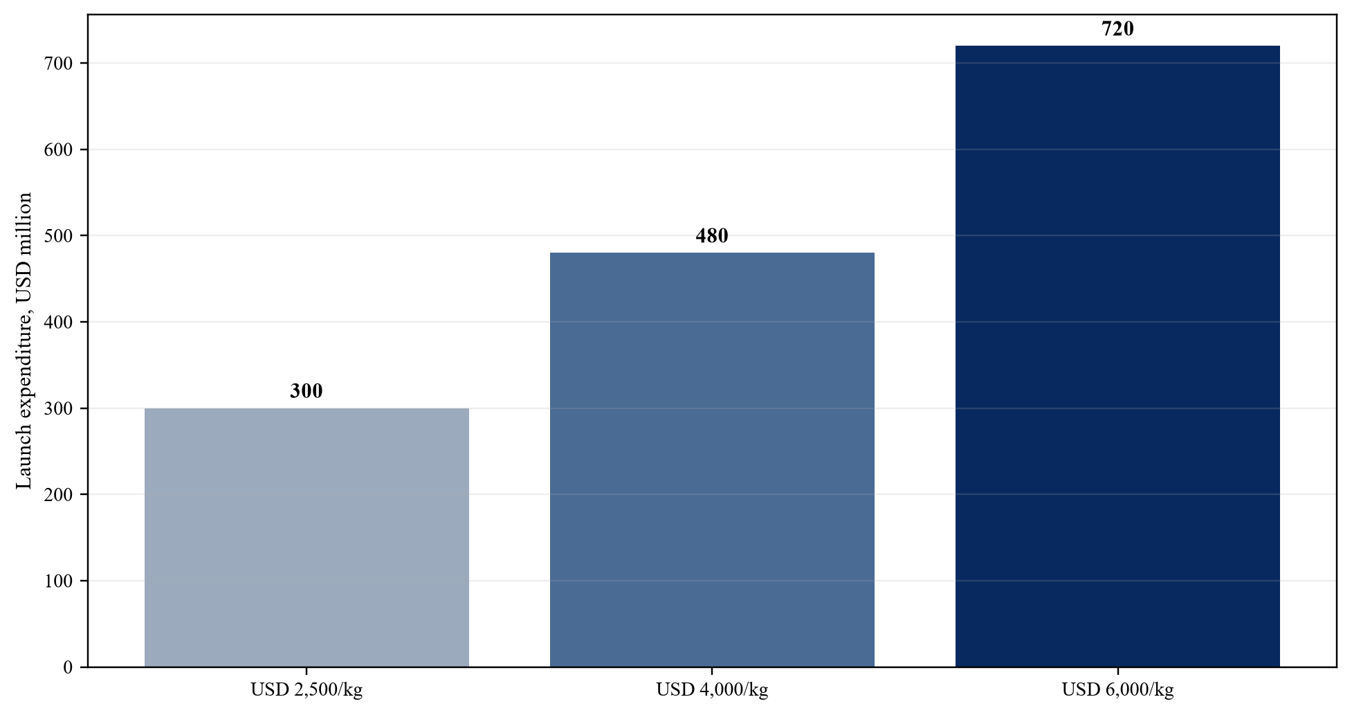
Wholly hypothetical; 120,000 kilograms of constellation launch mass.
| Capacity state | Minimum evidence | Valuation treatment |
|---|---|---|
| Planned | board plan and preliminary design | strategic option only |
| Manufactured | configuration record and factory acceptance | cost evidence subject to launch risk |
| Launched | launch confirmation | subject to deployment and commissioning risk |
| Commissioned | in-orbit acceptance test | service potential subject to customer acceptance |
| Service available | sustained power, thermal, compute and link test | probability-weighted operating capacity |
| Billable | customer acceptance, invoice and collection | recurring cash-flow evidence |
Proposed investment framework.
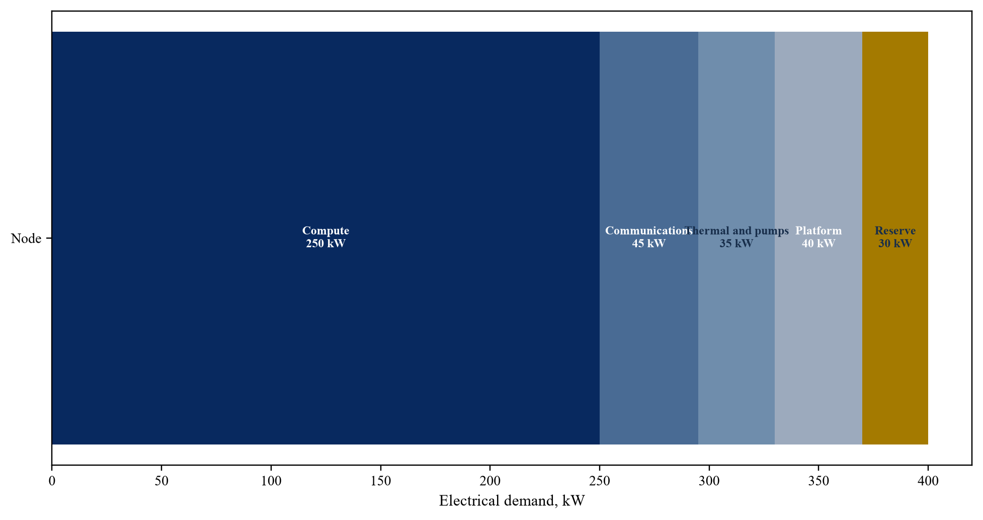
Wholly hypothetical 400-kilowatt total node demand.
| Workstream | Evidence | Decision use |
|---|---|---|
| Mass and interface | controlled mass budget, drawings and margins | vehicle fit and delivered cost |
| Contracted slot | executed agreement and payment schedule | cadence and funding timing |
| Integration | test plan, dispenser and separation evidence | deployment risk |
| Mission assurance | qualification, acceptance and anomaly process | loss probability |
| Insurance | indication, exclusions and limits | retained liquidity risk |
| Commissioning | in-orbit test and acceptance protocol | capacity recognition |
Proposed evidence requirements.
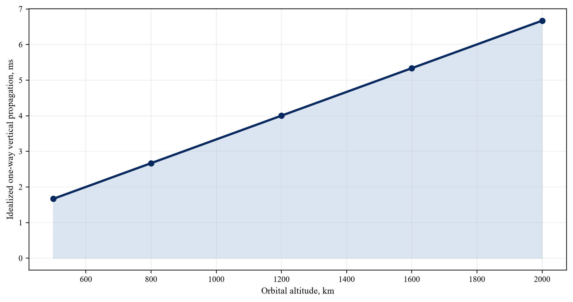
Physical distance divided by speed of light; excludes routing, slant range, processing and queue time.
| Issue | Minimum test | Cash-flow link |
|---|---|---|
| End-of-life solar output | orbit and degradation model | service-available energy |
| Battery life | cycle and thermal testing | eclipse capacity and replacement |
| Thermal rejection | correlated thermal-vacuum and in-orbit test | sustained compute duty cycle |
| Radiation tolerance | component and system-level test | failure and degradation reserve |
| Workload efficiency | representative end-to-end benchmark | billable throughput |
Proposed framework.
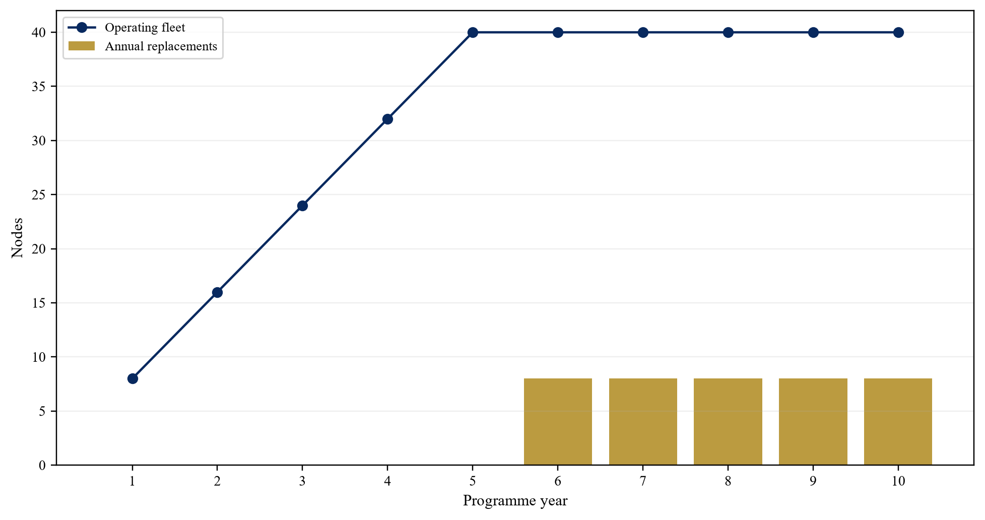
Wholly hypothetical; eight-node annual cohorts and five-year design life.
| Use | Central case |
|---|---|
| Development and qualification | 350 |
| Node manufacturing and integration | 2,450 |
| Launch expenditure | 480 |
| Ground and network systems | 320 |
| Contingency and working capital | 400 |
| Total | 4,000 |
Wholly hypothetical; USD million.
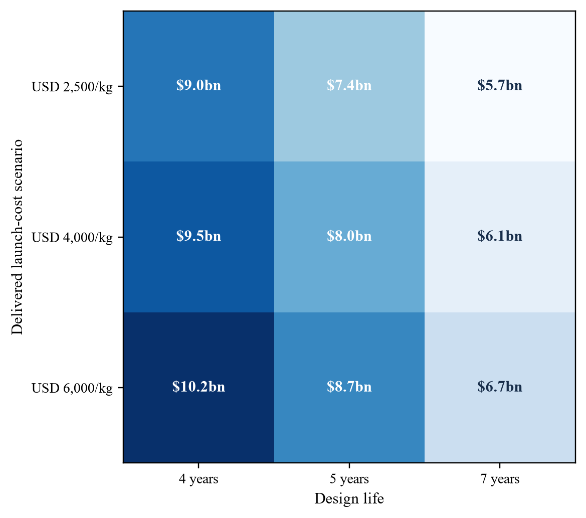
Wholly hypothetical total initial and ten-year replacement funding; USD billion.
| Gate | Evidence | Illustrative capital | Illustrative equity value |
|---|---|---|---|
| Architecture | regulatory path, integrated mass-power-thermal model | USD 40m | USD 80m |
| Flight demonstration | 50kW sustained compute and link acceptance | cumulative USD 180m | USD 260m |
| Commercial cluster | 500kW accepted service and customer minimum | cumulative USD 900m | USD 950m |
| Repeatable deployment | production yield, contracted cadence and replacement plan | project specific | cash-flow valuation |
Proposed framework with wholly hypothetical values.
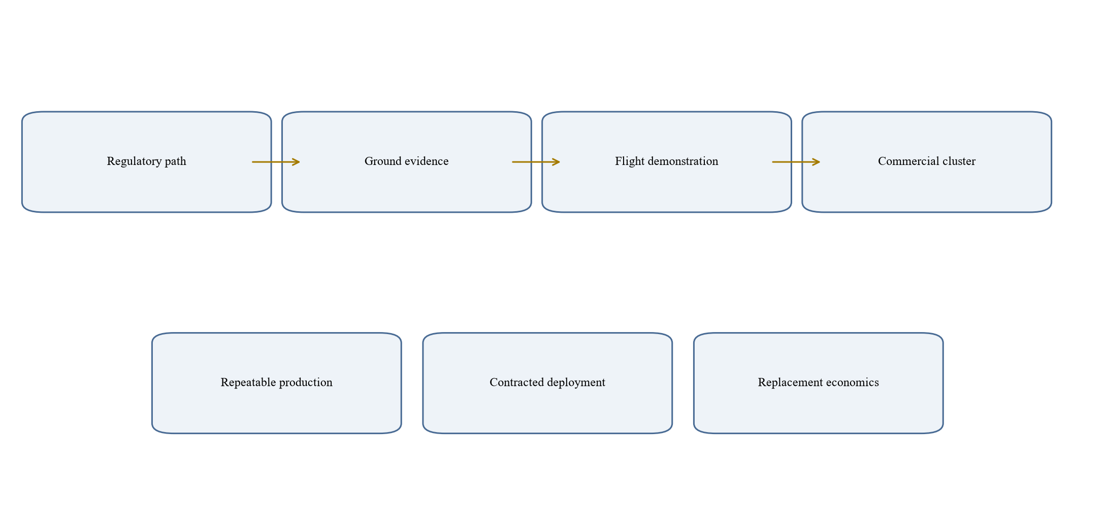
Proposed governance framework.
| Risk | Protection | Evidence or trigger |
|---|---|---|
| Authorization delay | staged closing or condition precedent | formal authorization milestone |
| Performance shortfall | milestone tranche and price adjustment | accepted in-orbit test |
| Launch concentration | provider diversification covenant | executed launch manifest |
| Supplier dependency | assignment, step-in and inventory rights | binding supply agreement |
| Replacement underfunding | restricted reserve and distribution test | approved lifecycle model |
| Customer non-conversion | contingent consideration | collected service revenue |
Terms require transaction-specific legal advice.
| Metric | Source | Trigger |
|---|---|---|
| Authorized and commissioned nodes | regulatory record and telemetry | schedule or scope variance |
| Service-available compute kW | power, thermal and workload tests | capacity shortfall |
| Billable utilization and collections | customer acceptance and bank records | demand variance |
| Launch cost and next available slot | executed contracts | funding or replacement risk |
| Failure and degradation by cohort | telemetry and anomaly reports | useful-life revision |
| Replacement reserve coverage | treasury and lifecycle model | distribution restriction |
Proposed framework.
Sources
- Federal Communications Commission, Space Bureau Accepts for Filing SpaceX Application for Orbital Data Centers, DA 26-113, 4 February 2026. Read the primary source
- Federal Communications Commission, Orbital Compute Inc. Application SAT-LOA-20260624-00251, August 2026 public notice. Read the primary source
- National Aeronautics and Space Administration, High Performance Spaceflight Computing. Read the primary source
- NASA Jet Propulsion Laboratory, High-Performance Space Computing Capability. Read the primary source
- European Space Agency Commercialisation Gateway, New Phi-lab in Sweden and the Rise of Edge Computing in Space. Read the primary source
- European Space Agency, Data Systems. Read the primary source
- National Aeronautics and Space Administration, State-of-the-Art of Small Spacecraft Technology 2026. Read the primary source
- National Aeronautics and Space Administration, Small Spacecraft Power Systems. Read the primary source
- National Aeronautics and Space Administration, Small Spacecraft Thermal Control. Read the primary source
- National Aeronautics and Space Administration, Small Spacecraft Structures Materials and Mechanisms. Read the primary source
- National Aeronautics and Space Administration, Small Spacecraft Communications. Read the primary source
- National Aeronautics and Space Administration, Small Spacecraft Avionics. Read the primary source
- Space Exploration Technologies Corp., Falcon 9 and Rideshare Program. Read the primary source
- United States Space Force, Launch Organization Leans into Modern Mission Assurance and Agile Integration, 2025. Read the primary source
- United States Government Accountability Office, Missile Warning Satellites Risks to Capability Delivery, GAO-26-107085. Read the primary source
- National Aeronautics and Space Administration, Orbital Debris Programme Office. Read the primary source
- National Aeronautics and Space Administration, NPR 8715.6B Requirements for Limiting Orbital Debris. Read the primary source
- National Aeronautics and Space Administration, NASA-STD-8719.14 Process for Limiting Orbital Debris. Read the primary source
- Federal Communications Commission, Space Innovation; Mitigation of Orbital Debris in the New Space Age, FCC 24-6. Read the primary source
- Federal Communications Commission, Space Innovation; Facilitating Capabilities for In-Space Servicing Assembly and Manufacturing, FCC 24-21. Read the primary source
- International Telecommunication Union, Radio Regulations. Read the primary source
- European Space Agency Space Solutions, SpaceCloud Demonstration. Read the primary source
- NASA Goddard Engineering and Technology Directorate, HPSC Radiation-Hardened Multicore Technology. Read the primary source
- NASA Goddard Engineering and Technology Directorate, Aerospace Flight Hardware and Technology. Read the primary source
- National Aeronautics and Space Administration Technical Reports Server, State-of-the-Art Small Spacecraft Technology, 2025. Read the primary source
- National Aeronautics and Space Administration Technical Reports Server, Introduction to the Orbital Debris Environment and Mitigation Requirements, 2025. Read the primary source
- IFRS Foundation, IFRS 13 Fair Value Measurement. Read the primary source
- IFRS Foundation, IAS 36 Impairment of Assets. Read the primary source
- IFRS Foundation, IAS 38 Intangible Assets. Read the primary source
- International Organization for Standardization, ISO 24113 Space systems Space debris mitigation requirements. Read the primary source
